Yes, you're right, that was my meaning also. I'm aware that some do exist, but I've never used one or seen one used as a clock for this application.
I seem to recall an app note from Linear Tech showing use of one of their ICs as an oscillator. It might have been a comparator.
Have you ever tried oscillators with analog ICs? I'm certainly not biased against them, I'd be curious to see how they perform.
Not as clock oscillators, no I haven't. I must admit to being a bit of a heretic when it comes to oscillators and perhaps I shouldn't even mention this... But I'm going to try one from ADI's new crop of DDS devices as a clock over the next few months. Sure their specs don't look nearly as good as XTALs but I'm curious to see if they do actually sound worse.

Surely a DDS has to start with a crystal clock? DDS is useful when you need to adjust the frequency or modulate it, or want a non-standard frequency. DDS are renowned for 'spurs', which could cause jitter. After travelling through a whole lot of gates the output will probably have picked up some random jitter too. Use a DDS when you want a signal. Use a clock when you want a clock!
I was indeed thinking of using the DDS with a crystal clock, yes. But no, it doesn't have to use one -there are MEMS options these days just as one alternative. Yes, I do want to have different frequencies - 44k1 and 48k and their multiples. Without a DDS, I'd need multiple oscillators and perhaps PLLs too. Using a DDS also allows me to experiment - for example deliberately jitter a clock and see if I can hear the effect. I'm rather curious to know if the incredibly low jitter numbers that get bandied around are based on audibility or marketing
Good ideea with jitter testing, but you can go only so low with a DDS, so you might still think you "miss" the difference because your "controlled" jitter is so "burried" in the native jitter.
On the other hand, my opinion (untested though) is that the mechanical jitter of the optical pick up (even after the RAM deshuffle, remains something in low-freq jitter range) is way bigger that the jitter produced by clocks - maybe even a DDS one. So you might be "on the money" with that aproach.
Of course that depends also of your ears, your headphones and your DAC (some claim that are more immune to jitter).
Also I think that even for the files stored on the HDD, the original optical jitter might remain "encrusted" in the files as missed/repeated or interpolated samples. But that is another story.
Last edited:
Good ideea with jitter testing, but you can go only so low with a DDS, so you might still think you "miss" the difference because your "controlled" jitter is so "burried" in the native jitter.
Another thing that's interesting to me is to explore the way the jitter varies with signal. I'm of the opinion (like you, untested) that correlated jitter is the main offender in respect of sound quality. There might be a way to artificially create correlated jitter using a DDS and explore the connection. Then perhaps if there is a connection the next step could be to synthesise 'anti-jitter' thereby cancelling jitter out. Dunno if it can be made to work though.
On the other hand, my opinion (untested though) is that the mechanical jitter of the optical pick up (even after the RAM deshuffle, remains something in low-freq jitter range) is way bigger that the jitter produced by clocks - maybe even a DDS one.
Bless you for the qualification!

The jitter from the pickup will be unquestionably large. The issue is the jitter at the DAC.
Opinions are nice, but it would be great if you could back up your opinion with some sort of evidence; diagrams, measurements, quoted texts etc.
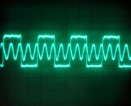
I was curious, so went and made a measurement myself. The attached photo of my 'scope screen shows two superimposed traces. The larger amplitude square wave is the bit clock trace from the SAA7310 decoder in my Arcam Alpha, the smaller amplitude triangle (ish) wave is the raw oscillator output from the SAA7220 (which includes an integrated crystal oscillator and is the master clock source for the player). These two traces were totally static in relation to each other.
These two traces are obviously synchronous; the output data rate from the decoder is controlled by the crystal oscillator. The player's bit clock is directly derived from the master clock, in this case BCK is a quarter of MCK. Nothing else is in play.
Interestingly you can also see a little of another of my points. The oscillator trace appears to be affected by the bit clock trace. This isn't my scope, it is due to the two signals being present on the same IC (the SAA7220). It's a very extreme case when you can just see it on a scope like that.
As for DDS, I wouldn't try it myself, but I wouldn't discourage others. I looked at a Rubidium clock once, it used a Rubidium oscillator as the frequency standard, which then fed a Analog Devices DDS IC. The unit could be programed via RS232 to output any clock frequency you wished within a certain range, maybe 1 to 30 MHz (very useful). The spec sheet included a phase noise plot which looked very good, so I think the idea may be worth trying. Personally, I'm just put off by the expense and complexity (which may be unjustified).
Attachments
Interestingly you can also see a little of another of my points. The oscillator trace appears to be affected by the bit clock trace. This isn't my scope, it is due to the two signals being present on the same IC (the SAA7220). It's a very extreme case when you can just see it on a scope like that.
Yes thanks for posting this - can't argue with perfectly visible patterning of the clock oscillator output
As for DDS, I wouldn't try it myself, but I wouldn't discourage others. I looked at a Rubidium clock once, it used a Rubidium oscillator as the frequency standard, which then fed a Analog Devices DDS IC. The unit could be programed via RS232 to output any clock frequency you wished within a certain range, maybe 1 to 30 MHz (very useful). The spec sheet included a phase noise plot which looked very good, so I think the idea may be worth trying. Personally, I'm just put off by the expense and complexity (which may be unjustified).
The cost and complexity would be that of the Rubidium clock (unjustified IMO for audio). The ADI parts cost a fistful of dollars each - the one I'm planning on playing with (AD9833) I've ordered on an eval board for about $15. There's the need for a passive high-order external filter too but that hardly will break the bank
$15 isn't too bad at all! I agree that a Rubidium clock is totally unnecessary for our application. I never thought seriously about buying one, just did some digging. Where did you get the eval board from?
One thing I like about DDS is how easily you can change frequencies. I can get 256fs crystals easily, 384fs and 768fs crystals with difficulty, and I can't get 1024fs crystals at all (some Sony players use them).
One thing I like about DDS is how easily you can change frequencies. I can get 256fs crystals easily, 384fs and 768fs crystals with difficulty, and I can't get 1024fs crystals at all (some Sony players use them).
This is the guy. I plan to see how far it overclocks as ADI's applications suggest the source clock should be at least 3X the maximum output clock frequency. What's really good about this chip though is its huge operating temperature range - to me that strongly suggests overclocking should be a doddle at room temp. Famous last words.....
<edit> To get those higher frequencies you could do worse than consider the LPC1113's PLL. I haven't tried it to just generate an output frequency but seeing as the price is under $2 for a whole CPU, the PLL comes effectively free Or in your case, the CPU comes free with the PLL. I'm currently running my CPU clock at 1280fs from a 256fs oscillator without any problems.
<edit> To get those higher frequencies you could do worse than consider the LPC1113's PLL. I haven't tried it to just generate an output frequency but seeing as the price is under $2 for a whole CPU, the PLL comes effectively free
Or in your case, the CPU comes free with the PLL. I'm currently running my CPU clock at 1280fs from a 256fs oscillator without any problems.
Last edited:
I think you may find that Rubidium has wonderful long term stability but lousy short-term stability i.e. high jitter. You could use Rubidium to phase lock a crystal, so you get the low jitter of a good crystal combined with the long-term accuracy of Rubidium but what is the point? Even someone with perfect pitch would not be able to distinguish between crystal accuracy and Rubidium accuracy. Part of good engineering is to use the right technology. For a CD player clock the right technology is well-engineered quartz.
With regard to professional opinions, the main difference between a professional opinion and an amateur one is that the professional one will usually cost you money but you can sue if it is negligently in error. I guess a licensed professional opinion either means it is even more expensive, or amateurs are not allowed to offer such opinions. Given the evidence to the contrary, one could argue that suggesting that transport jitter directly affects buffer RAM readout would be professional negligence if someone was paying for that opinion. Fortunately on here we don't have to pay.
With regard to professional opinions, the main difference between a professional opinion and an amateur one is that the professional one will usually cost you money but you can sue if it is negligently in error. I guess a licensed professional opinion either means it is even more expensive, or amateurs are not allowed to offer such opinions. Given the evidence to the contrary, one could argue that suggesting that transport jitter directly affects buffer RAM readout would be professional negligence if someone was paying for that opinion. Fortunately on here we don't have to pay.
Fortunately on here we don't have to pay.
I'm not so convinced myself that the 'fortunately' is always deserved. I notice a fair bit of professional advice given here which seems jolly sound and yet is ignored. Presumably because 'if its free, its worthless'. Plenty of people don't much value what they don't pay for IME.
If you must quote me, quote completelly what I have to say: "The RAM buffers in old CD controllers (90's era) are insufficient to eliminate completelly the transport jitter. The apport of this left-over jitter is higher than the one from the crystal refference".Given the evidence to the contrary, one could argue that suggesting that transport jitter directly affects buffer RAM readout would be professional negligence if someone was paying for that opinion. Fortunately on here we don't have to pay.
SoNic_real_one, I've produced evidence to back up my opinion on how decoders work and whether this so called 'transport jitter' exists. I see on other threads that you're still insisting that it does.
If you want to go on telling everyone about this transport jitter in lots of threads it would be great if you could produce some evidence to support your veiwpoint. You don't have to, but it'll hard for you to maintain credibility otherwise.
I'm not trolling, I'm genuinely interested in settling this issue.
- Status
- This old topic is closed. If you want to reopen this topic, contact a moderator using the "Report Post" button.
- Home
- Source & Line
- Digital Source
- SPDIF OUTPUT