...Looks like 25Vg2 works much better than 50Vg2 for low knee voltage. ....
The plate knee voltage is some fraction of Vg2.
For a True Tetrode the fraction is 1:1.
For some max-gain small-signal pentodes it may be 1:3. (100Vg2 makes plate knee ~~33V.)
Audio Power pentodes generally like Vg2 near raw B+ so strive for knee ratio nearer 1:10.
Large or fancy systems may allow a separate G2 supply, lower makes a low-Mu K-G2 "triode" system of higher purveyance, plate voltage may be raised, and now a low knee not so important. Looks like 1:3 or 1:4 in several of your hot-tube plots.
26A7 26.5 V on screen (26.5V at 0.6 Amp heater) (50V max for the screen, so could almost equal the 6DQ5 knee at 50V) (2 Watt max. plate diss.)
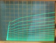
6DQ5 Knee curves (6.3V at 2.5 Amp heater) (notice the knee at 140 mA for 50V on the screen) (24 Watts max. plate diss.)
Not exactly audio, but I used 6DQ5's pre 1960 to generate -ve 1.5A pulses into 50R test systems. We needed nS rise times, I think these made it all the way in about <50 nS. Driven by EFP60s, a secondary emission pentode from Philips.
There is an article floating around where someone did build an audio amp using EFP60s. But not in the output stage.
And PP 6DQ5s would make a great amp.
No doubt 6DQ5 will make a good audio amplifier.
6HJ5 and 21/6LG6A are both derived from the 6DQ5.
6HJ5 has been popular in Pete Millett's 50 Watt Monoblock project and was used by George (Tubelab) in hot-rodding Pete's earlier DCPP amplifer.
6HJ5 gets you a no-plate-cap tube. And 21LG6A gets you a 28 Watt Sweep tube. ( with about 1.33x that for an audio tube rating, like 37 Watt)
All of them around $4 too. (26DQ5, 21LG6A, 6HJ5)
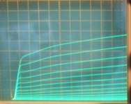
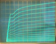
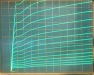
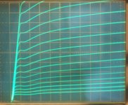
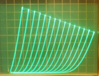
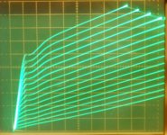
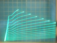
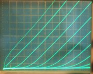
Here are some LV curves for the 21LG6A and 6HJ5:
(Vg2 at 25V, grid 1 steps -0.6 V down from 0V, 10 mA/div Vert., 10V/div Horiz.)
1) 21LG6A
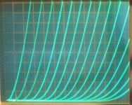
2) 6HJ5
I had to select thru some of those to find the good ones posted. Half of them were more like 40 to 50% higher knee voltage. Apparently that's not a very controlled parameter. It would be easy to test some tubes though, using just a 25V supply for screen, a variable 25V supply for plate, and a plate current meter (Vg1 connected to cathode).
I also traced 12AU7 and 12B4A triodes for LV operation. You want a low Rp triode for LV operation!
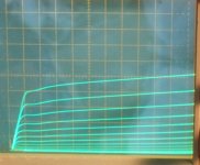
3) 12AU7 Raytheon black plate: -0.6 Vg1 steps, 0.5 mA/div Vert., 10V/div Horiz. (changed to 11 divisions across)
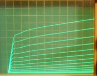
4) 12B4A GE: -1.5Vg1 steps, 2 mA/div Vert., 10V/div Horiz. (11 divisions across)
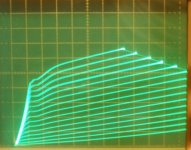
5) 26DQ5 at 25Vg2 again for ref. (same grid 1 steps -0.6 V down from 0V, 10 mA/div Vert., 10V/div Horiz. )
6) 21HB5A at 25 Vg2 again for ref.
6HJ5 and 21/6LG6A are both derived from the 6DQ5.
6HJ5 has been popular in Pete Millett's 50 Watt Monoblock project and was used by George (Tubelab) in hot-rodding Pete's earlier DCPP amplifer.
6HJ5 gets you a no-plate-cap tube. And 21LG6A gets you a 28 Watt Sweep tube. ( with about 1.33x that for an audio tube rating, like 37 Watt)
All of them around $4 too. (26DQ5, 21LG6A, 6HJ5)
Here are some LV curves for the 21LG6A and 6HJ5:
(Vg2 at 25V, grid 1 steps -0.6 V down from 0V, 10 mA/div Vert., 10V/div Horiz.)
1) 21LG6A
2) 6HJ5
I had to select thru some of those to find the good ones posted. Half of them were more like 40 to 50% higher knee voltage. Apparently that's not a very controlled parameter. It would be easy to test some tubes though, using just a 25V supply for screen, a variable 25V supply for plate, and a plate current meter (Vg1 connected to cathode).
I also traced 12AU7 and 12B4A triodes for LV operation. You want a low Rp triode for LV operation!
3) 12AU7 Raytheon black plate: -0.6 Vg1 steps, 0.5 mA/div Vert., 10V/div Horiz. (changed to 11 divisions across)
4) 12B4A GE: -1.5Vg1 steps, 2 mA/div Vert., 10V/div Horiz. (11 divisions across)
5) 26DQ5 at 25Vg2 again for ref. (same grid 1 steps -0.6 V down from 0V, 10 mA/div Vert., 10V/div Horiz. )
6) 21HB5A at 25 Vg2 again for ref.
Attachments
-
 rsz_21lg6a_25vg2_10ma_10vdiv.jpg101.7 KB · Views: 273
 -
 rsz_6hj5_25vg2_10ma_10vdiv.jpg119.3 KB · Views: 278
 -
 rsz_12au7_06vst_05ma_10vdiv_ray.jpg135.1 KB · Views: 280
 -
 rsz_12b4a_15vst_2madiv_10vdiv_ge.jpg129.7 KB · Views: 275
 -
 rsz_26dq5_25vg2_10ma_10vdiv.jpg129.5 KB · Views: 267
 -
 rsz_21hb5a_25vg2_10ma_10vdiv.jpg89.5 KB · Views: 39
Last edited:
An issue with running ECC88's at low voltage is the bias voltage become very small and then they tend to go into positive grid territory very easily. This will produce significant grid current and if this is attached to a POT will go scratchy in a matter of months. Better to use the ECC86, but the reason why they are ridiculously expensive is because Broskie produced an Aikido specifically for them. Overnight they went from pennys to more expensive than top flight ECC88's.
All things considered - best to work at higher voltages.
Shoog
All things considered - best to work at higher voltages.
Shoog
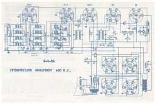
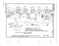
Farm Radios
Besides the 6 & 12 volt DC vacuum tube auto radios there was a line of radios built for 32 volts DC. This was a common voltage on farms in the 1930s before the rural areas were electrified. Unfortunately these systems used the same plugs, receptacles & so on as the 110 volt AC systems. So when the farming areas were finally hooked up to the grid many of the farm radios were simply plugged in by the unsuspecting user. Lots of smoke, so not many left for today’s collectors.
Notice in both schematics no HV supply at all. All the tubes ran on 32V DC & it looks like they did OK. All the output tubes are 48s. These had been developed specifically for the downtown areas of quite a few large cities still running on the Edison 110V DC system. New York City had a lot of that. I’ve read somewhere that part of downtown NYC still has part of the old DC system running in honor of Edison. Otherwise in those days some kind of inverter would have been required to get AC to run a transformer. That is an expensive solution to run a single radio.
I've often thought 25L6s could be successfully sub'd into these circuits in place of the 48s.
Attachments
...I've often thought 25L6s could be successfully sub'd into these circuits in place of the 48s.
Note that a pair of '48 is good for 5 Watts with 125V DC on hand, but nearer 0.156 Watts worked at 32V. That four-'48 radio was a whopping 0.3 Watts.
(This assume no grid current. Both those radios use grid transformers. They could be socking the grids "way positive" and at these conditions no harm and not much foul.)
The 0.15W would be a heck of a headphone amp.
'48 is actually marginally better conducting than the 25L6 and kin; considering the availability today, the 25L6 is for sure a go-to. There may be a $1 to equal it, but the hunt delays the build.
I curve traced a 12L6, 12W6 and 12DB5 at 25Vg2. These all seem to have the same specs in the GE handbook, but the 12L6 had the best knee curve shape.
All at 2 mA/div Vert., 10 V/div Horiz., -0.28V steps on grid 1 down from 0V.
1) Haltron 12L6
2) Sylvania 12W6
3) GE 12DB5
12/6DB5 is available on the ESRC $1 list. 12L6 looks better though.
Tubes types registered by:
12L6 GE 1954
6/12W6 CBS 1939
6/12DB5 CBS 1956
I checked a few other sweep tubes for knees at 25Vg2:
GE 6EX6 12V knee @ 32mA
Sylvania 6EX6 16V knee @ 36 mA
Sylvania 6EX6 11V knee @ 33 mA
RCA 6CB5A 11V knee @ 36 mA
GE 6CB5A 22V knee @ 44 mA
Sylvania 6CB5A 14V knee @ 36 mA
Amperex 12BQ6GA 16V knee @ 22 mA
Stromberg-Carlson 12AV5GT 15V knee @ 22 mA
Hard to say much with just single samples. Obviously not a well controlled parameter.
Attachments
Last edited:
Not exactly audio, but I used 6DQ5's pre 1960 to generate -ve 1.5A pulses into 50R test systems. We needed nS rise times, I think these made it all the way in about <50 nS. Driven by EFP60s, a secondary emission pentode from Philips.
There is an article floating around where someone did build an audio amp using EFP60s. But not in the output stage.
EFP60, not a power tube but developed for TV IF has a very large gain/bandwidth product. So it is able to provide a very low drive point impedance (16K) in this cct to the following grid. And still provide sufficient gain. In an RC coupled cct this results in lower distortion.
Used lots of them when they were available but never in an audio amp.
Attachments
EFP60
I don't think you will get much secondary emission with just 25 V B+ available.
Well, you are correct, 25V on the dynode wouldn't do much. But the schema shows it set at 200V, thru a 60K, 25W pot.
Think I posted the spec sheet for the EFP60 earlier, but here it is again. Shows 150V typically on the dynode, looks like the designer wants to push it a bit.
Attachments
'48 is actually marginally better conducting than the 25L6 and kin; ....
Dammit! Some fool keeps forgetting to attach his attachments!
Attachments
National Union NU2160 Space Charge Power Tube
Here is another example of space charge tube application. My recollection it didn't last too long, never saw one. Unable to find any data on it today other than what is in the article.
Sprinkle authored several articles at that time.
Here is another example of space charge tube application. My recollection it didn't last too long, never saw one. Unable to find any data on it today other than what is in the article.
Sprinkle authored several articles at that time.
Attachments
I got some new RCA 26A7 tubes in. So here are some curve tracings.
http://tubedata.milbert.com/sheets/049/2/26A7GT.pdf
All curves are 10 mA/div Vert. and 10V/div Horiz.
1) single pentode, +25Vg2, -0.6Vsteps on grid1
2) parallel pentodes, g2 drive, +1V steps on g2
3) Crazy drive parallel pentodes, +0.5V steps on g2
4) triode mode parallel, -2.5V steps on grid 1
The knee kinks are awful. Crazy drive doesn't help enough. But the triode mode looks quite nice, Mu around 2.9, Can get 30 mA at 10V min. in triode.
for comparison, the 21HB5, 21LG6, 6HJ5 and 12L6 again:
10V/div Horiz., +25Vg2, -g1 drive
5) 21HB5 10 mA/div Vert.
6) 21LG6 10 mA/div Vert.
7) 6HJ5 10 mA/div Vert.
8) 12L6 2 mA/div Vert.
I think I'll run off 21HB5 and 12L6 triode mode LV plots next.
Attachments
-
 rsz_26a7_t_25vsteps_10madiv_10vdiv_parallel.jpg120.4 KB · Views: 218
 -
 rsz_26a7_g2_g1_05vsteps_10madiv_10vdiv_parallel.jpg134.5 KB · Views: 224
 -
 rsz_26a7_1vg2steps_10madiv_10vdiv_parallel.jpg146.5 KB · Views: 218
 -
 rsz_26a7_25vg2_06vg1steps_10_madiv_10vdiv.jpg106.1 KB · Views: 224
 -
 rsz_21hb5a_25vg2_10ma_10vdiv.jpg89.5 KB · Views: 43
 -
 rsz_21lg6a_25vg2_10ma_10vdiv.jpg101.7 KB · Views: 37
 -
 rsz_6hj5_25vg2_10ma_10vdiv.jpg119.3 KB · Views: 34
 -
 rsz_12l6_25vg2_2madiv_10vdiv.jpg141.8 KB · Views: 43
Last edited:
Some triodes:
The 21HB5 in triode mode gets 12 mA at 10V minimum. (Vg1 = 0V for all) Mu 4.8
The 26LX6 in triode mode gets 20 mA at 10V minimum Mu 4
The 21LG6A in triode mode gets 11 mA at 10V minimum Mu 3.6
The 12L6 in triode gets 6 mA at 10V minimum. Mu 6
(the 26A7 in triode got 30 mA at 10V minimum, Mu 2.9)
5687 gets 1.5 mA at 10V
12B4 gets 3.2 mA at 10V
7119/E182CC gets 4.8 mA at 10V
6GM8 4.5 mA at 10V
6DJ8 3.4 mA at 10V
6CG7 2.4 mA at 10V
13FM7 GE 16 mA at 10V Mu 5.5
15FM7 Amperex 12 mA at 10V
13GF7 Sylvania 12 mA at 10V Mu 5.4
6S4A GE 0.8 mA at 10V
6S4A RCA 1.9 mA at 10V
Last edited:
That 30 mA at 10V for the 26A7 in triode above was using both sections in parallel.
So 26A7 in triode really should be listed as 15 mA for one section, Mu 2.9.
So that leaves us with best LV triode performers: 26A7, 21HB5, 13/15/6FM7, 13/10/6GF7, (26LX6 too expensive) and probably the other Mu 5.5 to 6 Vertical Amp tubes like:
6CY7, 6DE7, 6DR7, 6EA7, 6FY7, 6EW7, 6FD7, 6EM7, 6GL7, 6CK4, 10EG7
6GM8 for Mu 14, 7119 for Mu 24 (both expensive)
probably:
38/12/6HE7, some of the other (low internal Mu) TV Sweeps in triode mode, the big Vreg. tubes like: 7233, 7236, 5998, 6080, 6AS7... and of course the specific LV type tubes.
I played with the 26A7 to see if anything else useful could be found, and I found it will work well as a space charge triode.
Pic below is with both 26A7 sections in parallel. A positive 0.33V to 0.43V works well on grid1. Then grid 2 is used as the normal neg. going grid. (OOPs! note: I didn't quite get the base lined up on the bottom graticule line for the pic)
Scale is 2 mA/div Vert., 10V/div Horiz., -1V steps on grid2, +0.33 on grid1 (drawing total 1.4 mA thru grids 1 for both sections in parallel, so 0.23 mW diss for each grid 1)
Gives a Mu 17.5 triode with about 4.5 mA at 10V plate. So this is a 6GM8 (section) substitute!
(26A7 cost me about $3.50 with shipping from one Ebay listing, the other listings were -way- too expensive)
A potent (4.5 mA at 10V plate) and linear space charge tube, 26A7, Mu 17.5.
This same idea could probably be done with the TV Sweep tubes to get a higher Mu triode also.
21HB5A were $1, so I'll try one of them.
Attachments
Last edited:
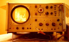
7788
Was used in the HP 1402A, dual channel vertical amp plug-in for the HP140 Series Scopes. My recollection just two of them in the entire scope other than the CRT. 20 MHz BW.
Data sheet shows the 7788 cranks on very quick.
Nice scope, easy to drive. With storage in the 141T vers & SA plug-ins it was a great success. Sold like crazy.
Video on P31 phosphor not great. Somewhere in the pile here is a better shot.
Attachments
Well, the TV Sweeps are not working well for space charge tubes. Having to draw 20 mA on grid 1 to get 1/2 ma plate current at Vp = 10V. The Mu's were up around 30. Tried several different sweep tubes. NG
Looks like maybe a low gm1 and very low Rp (Ri) is needed for space charge operation. So leaving out the sweep tubes.
Looks like maybe a low gm1 and very low Rp (Ri) is needed for space charge operation. So leaving out the sweep tubes.
Last edited:
Well, the TV Sweeps are not working well for space charge tubes. Having to draw 20 mA on grid 1 to get 1/2 ma plate current at Vp = 10V. The Mu's were up around 30. Tried several different sweep tubes. NG
Looks like maybe a low gm1 and very low Rp (Ri) is needed for space charge operation. So leaving out the sweep tubes.
12K5 pulls 10X plate current on the SPG. 12DL8, much better. Got an article here from the 40s, talks about excessive current when grid one of common pentodes is used as a SPG.
I will post it later, gotta get the file down to a size that can be posted here.
Attachments
PP 25L6 Receiver on 32 Volts
Looks like someone did it. In this persons vers he has used another 25L6 as a driver, more drive available than the other versions. Might even do some Class AB2.
6W6s are same as 25L6 so could be used in a trial. Something to do when it rains. A few hundreds of mWatts? Maybe!
And no hassle with a vibrator PS. Looks like about 30W all up on that farm supply. Anybody got a WinCharger?
Attachments
25L6 is OK, but I think we can do even better.
Using the 26A7, we could get 17.5 Mu for the 1st P-P gain stage using "space charge" mode. Which 26A7 seems to do -way- better than the official "space charge" tubes!
Then the output stage could be 26A7 in normal triode mode for linearity (Mu 2.9). Which gives us 15 mA peaks (10V min.) to work with in a P-P stage. (26A7 in pentode is just too non-linear)
Or 25/12L6 in pentode mode which gives us 20 mA peaks to work with.
Or 21HB5 in pentode mode which gives us 38 mA peaks to work with.
Or 21LG6A in pentode mode which gives us 53 mA peaks.
Or 26LX6 in pentode mode which gives us 100 mA peaks.
-----
But out of curiosity, I've looked at the 13FM7 tube's "other" Mu 66 triode #1 for the gain stage. (this is an el cheapo tube by the way)
In conventional triode we only get like 50 uA peak at 10V plate minimum.
But in positive grid1 territory it provides 4.7 mA (or more!) plate peak easily at 10 V min. (see pic below)
Measuring the grid current: at 1/2 way 2.35 mA plate it draws 0.5 mA thru the grid1 (at +1.9V on grid),
at 4.7 mA it draws 1.6 mA (at +3.8V on grid)
So if two of these tubes were in a P-P gain stage, driven by a CT'd 1:1 xfmr, the CT could provide the avg. DC current (0.5 + 0.5 mA) from a resistor pull up. So the AC -delta- current for max drive is: +1.1 mA - 0.5 mA = 0.6 mA for 1.9V+1.9V delta change.
So I guess that would be Rin = V/I = 3.8V/0.6mA = 6333 Ohms. ???? correct ???? (I'm not real sure about that math....)
We probably don't need all of 4.7 mA peak currents for an input gain stage, so this input impedance could easily be double or tripled. (and the min. plate voltage could go even lower than 10V) So I think this gain stage is do-able.
So if 6333 Ohms (or 2X or 3X that) can be driven by the source, we get 66 gain from the triode 1 side of the 13FM7. Then the triode 2 side (the big one) provides 12 mA peak currents to work with in a P-P output stage.
This would be the economy model. I think these tubes are like $3 now, but were $1 a while back.
I suppose two more 13FM7s could provide cathode followers (the big triodes) to drive the inputs if + and - grid 1 operation is used.
----
Another option I guess would be to drive the 13FM7 (big #2) outputs in P-P with positive grid drive for much higher output power, then use a second set of 13FM7 (big #2) triodes as followers for those positive grids. And the small 13FM7 (#1) triodes could be used in parallel P-P for a gain stage with neg. grids. (or just parallel the big #2 triodes in P-P and neg. grids for 24 mA peaks) Whatever works best... the tubes are cheap, just sockets to wire.
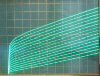
Picture below:
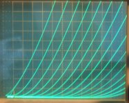
13FM7 triode side #1 (Mu 66), +0.25Vg1 steps, 1 mA/div Vert., 10V/div Horiz. (the neg. g1 curves look the same, just continue below the bottom curve)
Of course, if we have an inverter to provide +100V B+, this whole exercise is ridiculous.
Using the 26A7, we could get 17.5 Mu for the 1st P-P gain stage using "space charge" mode. Which 26A7 seems to do -way- better than the official "space charge" tubes!
Then the output stage could be 26A7 in normal triode mode for linearity (Mu 2.9). Which gives us 15 mA peaks (10V min.) to work with in a P-P stage. (26A7 in pentode is just too non-linear)
Or 25/12L6 in pentode mode which gives us 20 mA peaks to work with.
Or 21HB5 in pentode mode which gives us 38 mA peaks to work with.
Or 21LG6A in pentode mode which gives us 53 mA peaks.
Or 26LX6 in pentode mode which gives us 100 mA peaks.
-----
But out of curiosity, I've looked at the 13FM7 tube's "other" Mu 66 triode #1 for the gain stage. (this is an el cheapo tube by the way)
In conventional triode we only get like 50 uA peak at 10V plate minimum.
But in positive grid1 territory it provides 4.7 mA (or more!) plate peak easily at 10 V min. (see pic below)
Measuring the grid current: at 1/2 way 2.35 mA plate it draws 0.5 mA thru the grid1 (at +1.9V on grid),
at 4.7 mA it draws 1.6 mA (at +3.8V on grid)
So if two of these tubes were in a P-P gain stage, driven by a CT'd 1:1 xfmr, the CT could provide the avg. DC current (0.5 + 0.5 mA) from a resistor pull up. So the AC -delta- current for max drive is: +1.1 mA - 0.5 mA = 0.6 mA for 1.9V+1.9V delta change.
So I guess that would be Rin = V/I = 3.8V/0.6mA = 6333 Ohms. ???? correct ???? (I'm not real sure about that math....)
We probably don't need all of 4.7 mA peak currents for an input gain stage, so this input impedance could easily be double or tripled. (and the min. plate voltage could go even lower than 10V) So I think this gain stage is do-able.
So if 6333 Ohms (or 2X or 3X that) can be driven by the source, we get 66 gain from the triode 1 side of the 13FM7. Then the triode 2 side (the big one) provides 12 mA peak currents to work with in a P-P output stage.
This would be the economy model. I think these tubes are like $3 now, but were $1 a while back.
I suppose two more 13FM7s could provide cathode followers (the big triodes) to drive the inputs if + and - grid 1 operation is used.
----
Another option I guess would be to drive the 13FM7 (big #2) outputs in P-P with positive grid drive for much higher output power, then use a second set of 13FM7 (big #2) triodes as followers for those positive grids. And the small 13FM7 (#1) triodes could be used in parallel P-P for a gain stage with neg. grids. (or just parallel the big #2 triodes in P-P and neg. grids for 24 mA peaks) Whatever works best... the tubes are cheap, just sockets to wire.
Picture below:
13FM7 triode side #1 (Mu 66), +0.25Vg1 steps, 1 mA/div Vert., 10V/div Horiz. (the neg. g1 curves look the same, just continue below the bottom curve)
Of course, if we have an inverter to provide +100V B+, this whole exercise is ridiculous.
Attachments
Last edited:
- Status
- This old topic is closed. If you want to reopen this topic, contact a moderator using the "Report Post" button.
- Home
- Amplifiers
- Tubes / Valves
- space charge tube preamp