Next Cap: Hydlar Z.....Kevlar filled nylon
Hydlar Z.
This material is manufactured by Ensinger. It is described as a Kevlar filled nylon. Among the many claims are that wear rates will be 20 times lesser than with an unfilled nylon. Tensile strength spec is high. Here are some pics of the cap machined out of this stuff.

Above: Left: Hydlar Z cap Right: Original Nylatron cap

Above: Left: Hydlar Z cap Right: Original Nylatron cap
Note about the photos. These are fairly large image files. Probably larger than the server here wants to deal with. So if the proportions on some of these photos seems distorted, just click on the image to view the full image and proportions should be normal then.

Above: Hydlar Z cap resting loose on the knob end of the bearing shaft.

Above: Hydlar Z cap seated onto the bearing shaft.
next: Test record plots for the Hydlar Z cap. The same three tracks we've come to know so well.

Above: 300 hz @ +12 db.......HFN 001

Above: bass drum track..........Shure TTR 110

Above: Silent Groove..........HFN 001
These seem to conform to the norm")
I'll test the Hydlar Z cap on one week from today.
Then I'll summarize on the group of cap materials tested so far.
Following that I'll move on to one or two different bearing ball materials that seem interesting to try. For instance, I'll get a ceramic bearing ball. I think I'll also get a tungsten carbide bearing ball as well. I'll try Boca bearing to source these. They're convenient and friendly to deal with.
-Steve
Hydlar Z.
This material is manufactured by Ensinger. It is described as a Kevlar filled nylon. Among the many claims are that wear rates will be 20 times lesser than with an unfilled nylon. Tensile strength spec is high. Here are some pics of the cap machined out of this stuff.
Above: Left: Hydlar Z cap Right: Original Nylatron cap
Above: Left: Hydlar Z cap Right: Original Nylatron cap
Note about the photos. These are fairly large image files. Probably larger than the server here wants to deal with. So if the proportions on some of these photos seems distorted, just click on the image to view the full image and proportions should be normal then.
Above: Hydlar Z cap resting loose on the knob end of the bearing shaft.
Above: Hydlar Z cap seated onto the bearing shaft.
next: Test record plots for the Hydlar Z cap. The same three tracks we've come to know so well.
Above: 300 hz @ +12 db.......HFN 001
Above: bass drum track..........Shure TTR 110
Above: Silent Groove..........HFN 001
These seem to conform to the norm
I'll test the Hydlar Z cap on one week from today.
Then I'll summarize on the group of cap materials tested so far.
Following that I'll move on to one or two different bearing ball materials that seem interesting to try. For instance, I'll get a ceramic bearing ball. I think I'll also get a tungsten carbide bearing ball as well. I'll try Boca bearing to source these. They're convenient and friendly to deal with.
-Steve
Last edited:
I like your structured way you go about this Steve!
Seems like the material do not differ that much in the measurements.
Are you hearing any differences between the materials so far?
Regards
Nils
re listening:
I thought I heard something better with that Delrin thrust cap, but then the listening experience with that cap seemed to become normal and sound just as it had in recent times and no different from what it would when using different cap materials tried after it.
I'm not sure what it was with that Delrin cap. Perhaps the radically different silent groove report, right after the fresh installation, influenced my listening psychology.
I guess the shorter answer is "no", I haven't heard anything significantly different, except for that one anomoly with the Delrin. Which did not repeat.
Perhaps I'll "hear something" with a ceramic ball. I will probably mate the Ceramic bearing ball with one of the longer wearing materials.
-Steve
Hydlar Z after 1 week follow-up

Before and after. Left is fresh cap. Right is the cap after 1 week in use.
More pics:

Above: close-up of the Hydlar Z cap after 1 week in use. It is difficult to distinguish any evidence of wear, but there is some. It is just the way this material reflects light that makes it hard to focus our vision on. One thing that does become apparent; there appears to be some inclusions of unknown material just under the surface at the thrust area.

Above: close-up detail of the inclusion. When I made this cap, I also made two more from the same bar of stock. Those two do not show this included foreign material. (if it is foreign) But on the cap I used, I can't say if the inclusion was within the stock prior to machining, or if it became embedded into the material during machining.
These parts are small and require optical magnification in order to inspect the finished parts. I'm adapting to that.
Other notes:
Sound quality. I did not hear any notable differences between this Hydlar-Z cap and any of the other caps within this test. I will summarize between the caps and include measurements of the wear spot on each cap reported for comparison.
-Steve
Before and after. Left is fresh cap. Right is the cap after 1 week in use.
More pics:
Above: close-up of the Hydlar Z cap after 1 week in use. It is difficult to distinguish any evidence of wear, but there is some. It is just the way this material reflects light that makes it hard to focus our vision on. One thing that does become apparent; there appears to be some inclusions of unknown material just under the surface at the thrust area.
Above: close-up detail of the inclusion. When I made this cap, I also made two more from the same bar of stock. Those two do not show this included foreign material. (if it is foreign) But on the cap I used, I can't say if the inclusion was within the stock prior to machining, or if it became embedded into the material during machining.
These parts are small and require optical magnification in order to inspect the finished parts. I'm adapting to that.
Other notes:
Sound quality. I did not hear any notable differences between this Hydlar-Z cap and any of the other caps within this test. I will summarize between the caps and include measurements of the wear spot on each cap reported for comparison.
-Steve
Cap material summary
Cap Material Summary:
At this point I've tried 6 different materials for the thrust cap job. During this trial period I have observed some differences in the rate of wear between these materials over the 1 week test period that has been in use for each material. The following reports the diameter of the wear spot on each cap within this report.
Instrument in use: a 10x Loupe with reticle manufactured by Peak (Japan). This reticle is in decimal inches and resolves to .005 graduations.
(note: this symbol Ø is gd&t for 'diameter'.)

Torlon 4301 at 1 week. Wear: Ø.025 inches

Torlon 4203 at 1 week. Wear: Ø.025 inches

Delrin at 1 week. Wear: Ø.035 inches

MDS filled nylon at 1 week. Wear: Ø.040 inches
Kevlar filled nylon (Hydlar-Z) at 1 week. Wear: Ø ? imperceptible. In different light and without magnification I can barely make out a shiny spot, but can not reliably report a diameter value. Regardless, this indicates minimal wear. Perhaps the lowest in the group.
For reference:

original equipment thrust cap: I think the material is nylatron but will not bet on it. Period of use: 37 years. Wear: Ø.095 inches
Other notes: The test record report graphs were produced before and after the 1 week period on each cap material. I saw no appreciable change between fresh and 1 week in this reporting. Except for the Delrin results which I'm tempted to toss out as an unexplained anomaly and I doubt its validity. Also it is useful to take note of the test record reporting on the original equipment 37 year old and well worn cap compared to any of these new materials. Here is a comparison between the OEM cap (worn) and the Torlon 4203 cap just freshly installed.

OEM cap silent groove plot: 37 years of use

Torlon 4203 silent groove plot: freshly installed.
Compare between the two silent groove plots at 100 hz. The OEM cap reports just slightly quieter than does the freshly installed Torlon 4203 cap.
Fwiw, I heard no difference.
Next: testing different thrust balls.
-Steve
Cap Material Summary:
At this point I've tried 6 different materials for the thrust cap job. During this trial period I have observed some differences in the rate of wear between these materials over the 1 week test period that has been in use for each material. The following reports the diameter of the wear spot on each cap within this report.
Instrument in use: a 10x Loupe with reticle manufactured by Peak (Japan). This reticle is in decimal inches and resolves to .005 graduations.
(note: this symbol Ø is gd&t for 'diameter'.)
Torlon 4301 at 1 week. Wear: Ø.025 inches
Torlon 4203 at 1 week. Wear: Ø.025 inches
Delrin at 1 week. Wear: Ø.035 inches
MDS filled nylon at 1 week. Wear: Ø.040 inches
Kevlar filled nylon (Hydlar-Z) at 1 week. Wear: Ø ? imperceptible. In different light and without magnification I can barely make out a shiny spot, but can not reliably report a diameter value. Regardless, this indicates minimal wear. Perhaps the lowest in the group.
For reference:
original equipment thrust cap: I think the material is nylatron but will not bet on it. Period of use: 37 years. Wear: Ø.095 inches
Other notes: The test record report graphs were produced before and after the 1 week period on each cap material. I saw no appreciable change between fresh and 1 week in this reporting. Except for the Delrin results which I'm tempted to toss out as an unexplained anomaly and I doubt its validity. Also it is useful to take note of the test record reporting on the original equipment 37 year old and well worn cap compared to any of these new materials. Here is a comparison between the OEM cap (worn) and the Torlon 4203 cap just freshly installed.
OEM cap silent groove plot: 37 years of use
Torlon 4203 silent groove plot: freshly installed.
Compare between the two silent groove plots at 100 hz. The OEM cap reports just slightly quieter than does the freshly installed Torlon 4203 cap.
Fwiw, I heard no difference.
Next: testing different thrust balls.
-Steve
Last edited:
A ceramic bearing ball
Thrust Balls:
Does it make sense to try different materials and grades of the bearing ball in the thrust end of the platter bearing? Let's see if we can't prove it one way or another.
Ceramic: 9/32" SiN4 Ceramic grade 5 (sourced from Boca Bearing Company)

Prior to assembly, and just for this photo, the ceramic ball is perched in the cup end of the thrust cap that will be used. That is the only way I could get the ball to hold still for the photo. Either that or level my photo table as closely as one would a billiard table. Looking close, the ball has a highly polished finish that reflects the setup for taking the photo. And also tiny bits of dust clinging tenaciously to its outer surface. I wiped the ball with a chamoise several times to no effect.

Looking at the interior of a freshly made Torlon 4203 thrust cap.

Exterior detail. The Torlon 4203 cuts fairly clean with commonly used lathe tool bits of carbide and high speed steel. A hand held metal file was used to apply edge breaks while the part was turning in the lathe. The part was cut complete in a single setup. Turning the OD. Facing off the open end. Drilling with a center drill to open up for the boring bar, which was used to cut the ID for size and also used to cut the interior face to depth. To establish the length of the part, a parting off tool was used. To finish it, a secondary operation was applied using a bench lap to lap the thrust face of this part into a smooth condition. This process has been used on all of the above thrust caps, including this one.
Assembly.
Replacing the plastic thrust cap at the tip end of the bearing shaft is somewhat simpler than replacing the bearing ball. For the cap all one needs to do is leave the player upright and disassemble the platter from the motor unit, then remove another 'gazillion' machine screws an assortment of keepers and cover plates......and a platter brake assembly. After that we can -gingerly- lift the rotor, the very valuable rotor, up out of its bearing housing. To understate it, Technics has their player securely buttoned up and held together tight.
But to remove the bearing ball at the bottom of the bearing housing, one needs to hold the motor unit upside down safely and securely, then unscrew another gazillion machine screws to remove the bottom cover. Having done that it exposes the main-board circuitry and the all important platter bearing thrust cup sticking up in the middle of it all. But one needs be careful not to disturb the printed circuit boards and the small city of electronics parts attached to them. Or perhaps it is better to remove the printed circuit board prior to removing the bottom bearing thrust cup. The parts on this player are rare and valuable. See elsewhere in this article (sp10_dis ) for some details on removing the platter bearing thrust cup. It is held on by threads and a generous amount of thread sealer. Care needs be taken. Care and technique...if you want to avoid damage.

The bottom thrust cup once removed.

Looking into the thrust cup. Notice the threads, the spot face at its bottom and the prominent crater that indicates previous use. The bearing ball holds a fixed position, does not turn, and is held in firm contact with both this cap and the side walls of the bearing housing where it resides. Notice two bits of annotation. A number 1, indicating the spot face surface, and a number 2, indicating a wear spot, by means of an arrow pointing to it, where the bearing ball makes firm contact with the cup.
Let's measure the wear spot to see how deep the crater is:

A granite based drop indicator is used to measure the wall thickness at the cup bottom. This shot shows the indicator almost set to zero. This was adjusted prior to making measurements to exact zero on the big dial. Also take note of the smaller dial within the face of the indicator. It is also set to zero. That smaller dial counts revolutions of the large needle. One rev is .050 inches.

Checking the spot face area for thickness. What's the reading? Reading the two dials I get .096 inches of wall thickness between the cup bottom and the spot faced surface.

Checking in the center of the wear crater. What's the reading? Look at it two ways. Compare this reading to the previous reading taken on the spot face surface to get a simple depth read. Just subtract the smaller value (crater read) from the larger value (spot face read) to find depth of the crater. I get just a touch over .001" of depth in that crater. Not very deep. You can also figure wall thickness at the crater bottom simply by reading the dials. For that I get .095 inches. Isn't this fun.
While I've got the thing apart let's take a look at some other sizes.

I'm using a Mahr gage to find the size of the bearing housing ID. I used the Mahr gage to scan up down and around within this housing. The gage indicates a straight through bearing bore with no relief areas, that is straight and round. Variation of the readings was less than .0002 inches. This is good news as it means there is little if any wear in this bore.

Using a micrometer I'm gaging the diameter of the original equipment thrust bearing ball. Guess what; the .2815 inch ball is closely size for size with the bearing housing inside diameter. This also works out to a fractional inch size; 9/32". Go figure. A Japanese manufacturer, where the metric system dominates, choses a 9/32 inch bearing size for their top of the line record player. What this leaves us with is a bearing ball that is size for size with the bearing housing it must fit into. A small amount of force is used to assemble and disassemble the ball from the housing each time. That way the ball is not allowed to move, not even slightly, while doing its job at the bottom of the platter bearing.

Checking the new SiN4 Ceramic grade 5 bearing ball. Funny, it checks .0013 inches larger in diameter than the oem ball. And this is over the nominal 9/32" stated size for this bearing. What it means is that if I use this bearing ball it will need to be pressed into the bottom end of the bearing housing. Should I do that or should I find another ball? As it turned out I just placed the ceramic ball on the opening end of the bearing housing, then screwed the bottom cup down over it to press the ball into position. The required force did not seem excessive to my calibrated wrist as I wrenched the threaded cup down over its fitting.
Test Record Plots for the ceramic ball:

300 hz @ +12 db.......HFN 001

bass drum .......... Shure TTR110

Silent Groove plot.........HFN 001
As I review this group of test plots and compare against previous plots from the different materials while using the oem bearing ball, I see that there are some small differences in the measurements. In particular as I look at the silent groove plot exclusively I can find differences between them on the order of 2 to 3 db. And that is all. This is not significant.
Listening notes to come.
Thrust Balls:
Does it make sense to try different materials and grades of the bearing ball in the thrust end of the platter bearing? Let's see if we can't prove it one way or another.
Ceramic: 9/32" SiN4 Ceramic grade 5 (sourced from Boca Bearing Company)
Prior to assembly, and just for this photo, the ceramic ball is perched in the cup end of the thrust cap that will be used. That is the only way I could get the ball to hold still for the photo. Either that or level my photo table as closely as one would a billiard table. Looking close, the ball has a highly polished finish that reflects the setup for taking the photo. And also tiny bits of dust clinging tenaciously to its outer surface. I wiped the ball with a chamoise several times to no effect.
Looking at the interior of a freshly made Torlon 4203 thrust cap.
Exterior detail. The Torlon 4203 cuts fairly clean with commonly used lathe tool bits of carbide and high speed steel. A hand held metal file was used to apply edge breaks while the part was turning in the lathe. The part was cut complete in a single setup. Turning the OD. Facing off the open end. Drilling with a center drill to open up for the boring bar, which was used to cut the ID for size and also used to cut the interior face to depth. To establish the length of the part, a parting off tool was used. To finish it, a secondary operation was applied using a bench lap to lap the thrust face of this part into a smooth condition. This process has been used on all of the above thrust caps, including this one.
Assembly.
Replacing the plastic thrust cap at the tip end of the bearing shaft is somewhat simpler than replacing the bearing ball. For the cap all one needs to do is leave the player upright and disassemble the platter from the motor unit, then remove another 'gazillion' machine screws an assortment of keepers and cover plates......and a platter brake assembly. After that we can -gingerly- lift the rotor, the very valuable rotor, up out of its bearing housing. To understate it, Technics has their player securely buttoned up and held together tight.
But to remove the bearing ball at the bottom of the bearing housing, one needs to hold the motor unit upside down safely and securely, then unscrew another gazillion machine screws to remove the bottom cover. Having done that it exposes the main-board circuitry and the all important platter bearing thrust cup sticking up in the middle of it all. But one needs be careful not to disturb the printed circuit boards and the small city of electronics parts attached to them. Or perhaps it is better to remove the printed circuit board prior to removing the bottom bearing thrust cup. The parts on this player are rare and valuable. See elsewhere in this article (sp10_dis ) for some details on removing the platter bearing thrust cup. It is held on by threads and a generous amount of thread sealer. Care needs be taken. Care and technique...if you want to avoid damage.
The bottom thrust cup once removed.
Looking into the thrust cup. Notice the threads, the spot face at its bottom and the prominent crater that indicates previous use. The bearing ball holds a fixed position, does not turn, and is held in firm contact with both this cap and the side walls of the bearing housing where it resides. Notice two bits of annotation. A number 1, indicating the spot face surface, and a number 2, indicating a wear spot, by means of an arrow pointing to it, where the bearing ball makes firm contact with the cup.
Let's measure the wear spot to see how deep the crater is:
A granite based drop indicator is used to measure the wall thickness at the cup bottom. This shot shows the indicator almost set to zero. This was adjusted prior to making measurements to exact zero on the big dial. Also take note of the smaller dial within the face of the indicator. It is also set to zero. That smaller dial counts revolutions of the large needle. One rev is .050 inches.
Checking the spot face area for thickness. What's the reading? Reading the two dials I get .096 inches of wall thickness between the cup bottom and the spot faced surface.
Checking in the center of the wear crater. What's the reading? Look at it two ways. Compare this reading to the previous reading taken on the spot face surface to get a simple depth read. Just subtract the smaller value (crater read) from the larger value (spot face read) to find depth of the crater. I get just a touch over .001" of depth in that crater. Not very deep. You can also figure wall thickness at the crater bottom simply by reading the dials. For that I get .095 inches. Isn't this fun.
While I've got the thing apart let's take a look at some other sizes.
I'm using a Mahr gage to find the size of the bearing housing ID. I used the Mahr gage to scan up down and around within this housing. The gage indicates a straight through bearing bore with no relief areas, that is straight and round. Variation of the readings was less than .0002 inches. This is good news as it means there is little if any wear in this bore.
Using a micrometer I'm gaging the diameter of the original equipment thrust bearing ball. Guess what; the .2815 inch ball is closely size for size with the bearing housing inside diameter. This also works out to a fractional inch size; 9/32". Go figure. A Japanese manufacturer, where the metric system dominates, choses a 9/32 inch bearing size for their top of the line record player. What this leaves us with is a bearing ball that is size for size with the bearing housing it must fit into. A small amount of force is used to assemble and disassemble the ball from the housing each time. That way the ball is not allowed to move, not even slightly, while doing its job at the bottom of the platter bearing.
Checking the new SiN4 Ceramic grade 5 bearing ball. Funny, it checks .0013 inches larger in diameter than the oem ball. And this is over the nominal 9/32" stated size for this bearing. What it means is that if I use this bearing ball it will need to be pressed into the bottom end of the bearing housing. Should I do that or should I find another ball? As it turned out I just placed the ceramic ball on the opening end of the bearing housing, then screwed the bottom cup down over it to press the ball into position. The required force did not seem excessive to my calibrated wrist as I wrenched the threaded cup down over its fitting.
Test Record Plots for the ceramic ball:
300 hz @ +12 db.......HFN 001
bass drum .......... Shure TTR110
Silent Groove plot.........HFN 001
As I review this group of test plots and compare against previous plots from the different materials while using the oem bearing ball, I see that there are some small differences in the measurements. In particular as I look at the silent groove plot exclusively I can find differences between them on the order of 2 to 3 db. And that is all. This is not significant.
Listening notes to come.
Thank you for taking the trouble to do and post all this work!
Great job.
Ditto - fascinating reading!
Ceramic bearing ball 1 week out
It has been one week since I installed the ceramic bearing ball and a freshly made Torlon 4203 thrust cap. To follow up I've removed the rotor from the sp10 chassis to examine thrust pad wear. Here's a photo of it.

The wear spot diameter measures .030 inches in diameter. I find this approximately in keeping with the 1 week wear spot notes reported in post#265 (cap summary)
next: the traditional test record spectrum plots:

300 hz @ +12 db.......HFN 001

bass drum .......... Shure TTR110

silent groove ............. HFN 001
Looking at the silent groove plot I can find a few DB of variation between the fresh and 1week plots in this configuration. But nothing more than that. Which I consider to be not significant.
I intend to keep this configuration for a few months of operation while I focus on other projects. In particular, I have a TD124 project that I am gearing up to begin. While that goes on I'll simply use this SP10 mk2, as it is currently configured, to spin records with. Trust me, I'm not suffering with this motor unit.
Listening notes:
I can't say that I have heard anything overtly different between the the different thrust cap materials, or in this one SiN4 Ceramic grade 5 thrust ball. On the other hand I've heard no negatives either. Sound quality is currently as good as I've heard so far. So I'll keep it this way in the near term.
After completing a couple of other projects (Thorens projects) I'll return to finish out the refurbishment of this player. Because this player appears to operate like it should, "I won't disturb what ain't busted." Not for now. But soon. I need to know how old those electrolytics are on the pcbs.
-Steve
It has been one week since I installed the ceramic bearing ball and a freshly made Torlon 4203 thrust cap. To follow up I've removed the rotor from the sp10 chassis to examine thrust pad wear. Here's a photo of it.
The wear spot diameter measures .030 inches in diameter. I find this approximately in keeping with the 1 week wear spot notes reported in post#265 (cap summary)
next: the traditional test record spectrum plots:
300 hz @ +12 db.......HFN 001
bass drum .......... Shure TTR110
silent groove ............. HFN 001
Looking at the silent groove plot I can find a few DB of variation between the fresh and 1week plots in this configuration. But nothing more than that. Which I consider to be not significant.
I intend to keep this configuration for a few months of operation while I focus on other projects. In particular, I have a TD124 project that I am gearing up to begin. While that goes on I'll simply use this SP10 mk2, as it is currently configured, to spin records with. Trust me, I'm not suffering with this motor unit.
Listening notes:
I can't say that I have heard anything overtly different between the the different thrust cap materials, or in this one SiN4 Ceramic grade 5 thrust ball. On the other hand I've heard no negatives either. Sound quality is currently as good as I've heard so far. So I'll keep it this way in the near term.
After completing a couple of other projects (Thorens projects) I'll return to finish out the refurbishment of this player. Because this player appears to operate like it should, "I won't disturb what ain't busted."
Not for now. But soon. I need to know how old those electrolytics are on the pcbs.-Steve
Perhaps greater gains can be had by installing a mechanical drain for the vibration of the motor unit? Just a bolt to snug up to the bottom of the bearing attached to the plinth ought to work wonders.
if the plinth is made of something which damps, otherwise it could make matters worse!
Thanks for the reminders. It has been part of my plan to incorporate a bearing drain into my Mule plinth. In fact I have some cutouts in the bottom plate of the plinth that will hold the necessary components of a bearing drain. ie: plate with threaded hole to accommodate the drain bolt part of it.

I had also thought that this idea of a bearing drain also holds some opportunities to enhance the performance of such a thing. For instance, the bolt that is used to make contact with the bottom main bearing cap can contain some damping elements. Like maybe some solid graphite machined into a shape for the application. Perhaps even a compression type of spring tensioner to hold the graphite bar against the bearing cap.
And also the fixture (bar stock) with the threaded hole can be of a material inclined to afford some damping to the bolt....or perhaps of a material inclined to conduct the vibes into a kind of dissipation chamber (like sand box or lead shot chamber) Details to be worked out. ( for the moment just thinking unrestrained by any reality.)
For the moment I've been working on other projects while I simply spin records on the SP10. Sound quality coming off this rig is quite good. And the deck operates without flaw. Nothing broken, therefore nothing to fix. but I will return to the sp10 project in a month or two. And I will try out some ideas with the bearing drain.
-Steve
ps: sp10 project summary page: sp10_Mule
I think Cats Squirrel's comment is very relevant. How and to what you drain is important. I have used SP10 mk II as my main TT's for 15 years and currently have two operational, another two in storage and one incomplete as a parts donor. I noticed early on that the main bearing cap is just about perfectly flush with the rubber membrane that covers the hole in the base cover casting. When the chassis is sitting on a flat surface, the rubber membrane/bearing cap sits flush on the surface. I have always mounted my SP10's sitting on one or two sheets of lead. My preferred cast resin plinths have internal depth calculated to accommodate the lead sheets. The resin plinth are superbly damped anyway and the lead is just icing the cake. I would be very wary of spring loaded coupling of a drain component. This just introduces a potential vibrating component just where it can do the most sonic harm.Thanks for the reminders. It has been part of my plan to incorporate a bearing drain into my Mule plinth. In fact I have some cutouts in the bottom plate of the plinth that will hold the necessary components of a bearing drain. ie: plate with threaded hole to accommodate the drain bolt part of it.
I had also thought that this idea of a bearing drain also holds some opportunities to enhance the performance of such a thing. For instance, the bolt that is used to make contact with the bottom main bearing cap can contain some damping elements. Like maybe some solid graphite machined into a shape for the application. Perhaps even a compression type of spring tensioner to hold the graphite bar against the bearing cap.
And also the fixture (bar stock) with the threaded hole can be of a material inclined to afford some damping to the bolt....or perhaps of a material inclined to conduct the vibes into a kind of dissipation chamber (like sand box or lead shot chamber) Details to be worked out. ( for the moment just thinking unrestrained by any reality.)
And I will try out some ideas with the bearing drain.
-Steve
On a general note, the bearing material test results seem to indicate that the bearing material is not a limiting factor in the SP10 mk II performance, as it is currently set up. I take this as encouraging. My experience is that plinth materials and construction do make audible differences to the performance. Maybe your measurement methodology can be applied to evaluating differences in plinth construction. I am in the high mass + stiffness + damping camp with cast isopthalic resin/fibreglass strand construction.
Polyester resins, most used resin systems, particularly in the marine industry
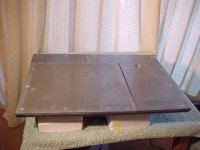
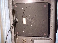
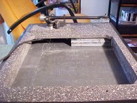
The first four pictures show my original Corian plinth with lead sheet damping. The last photo is of my resin/fibreglass plinth, base thickness 30 mm. Both unloaded plinths are approx 30 kg weight.
Attachments
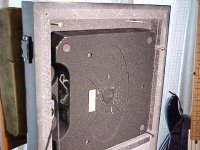
excellent work, bon, to be taken seriously. But I have found Corian not to be good at damping, whereas the isophthalic polyester resin, in combination with the right materials, is very good, unusual in a stiff material.
I am in the 'damping first, stiffness and mass second' camp.
"Taking moderation to excess..."
I am in the 'damping first, stiffness and mass second' camp.
"Taking moderation to excess..."
Last edited:
Then the others who read these threads, try it and aren't so particular about how they dispose of the excess shot. etc.
I bought some 0.125" sheet lead to provide plinth and dust cover damping and isolation from the environment, both mechanical and air, as much as possible for my LP12. In effect, I greatly improved the isolation between the environment and the spring suspended element which includes the motor, platter and tonearm mounting. I put a sealed lead core in my version of the turntable bottom plate (& also used that to balance out the turntable mass irregularities - important because I am suspending the entire turntable and its base on four "Airpods" which are magnetically suspended air barrier isolation stands.
I sandwiched most of the remaining lead sheet between wood panels at the sides of the dust cover which added considerable mass damping without inhibiting viewability. The dust cover front and back panels are 0.25" plexiglass and the top is two sandwiched 0.125" thick layers of plexiglass. I hear a real improvement in detail at high SPL levels with this approach when the turntable is in the listening room.
I melted down all the remaining lead I had left into molds and used them as anti-rocking weights at the tops of my HT speakers. Basically, no waste lead left
Last edited:
Perhaps "mass damping" was not the best reference. I was of course, not considering lead as a damping material in and of itself, but the overall damping effect in a layered constrained mass system with wood outer panels. I was also thinking of the increased vibration isolation qualities of largely increased panel mass and the on the air pods where the air pods damping corner frequency was lowered by adding the lead fill.
Last edited:
Thinking about the bearing drain idea
I think the way to proceed forward is to itemize a list of design ideas to be studied, then in a methodical way, research each idea. Find the most merit-worthy. Develop a design to implement it, then build a prototype for measurement.
At this point I think I see two ideas forming.
1) alternate plinth designs
2) incorporating a bearing drain
I want to isolate my measurements between the two ideas above. I'll study the bearing drain idea while continuing to use my test mule plinth. Once I have some measurements recorded, using a bearing drain, I'll look at alternate plinth designs and ultimately take measurements again using different plinths, with and without bearing drain.
Another thought. Even the name of the function, bearing drain, describes its intended function. A 'drain', like the drain in your kitchen sink sends excess tap water into the city sewer system, the bearing drain is fantasized as sending unwanted bearing noise into never never land where it is, apparently, never heard again. Fantasy or real?
I think we should consider this in depth. Prove it or dis-prove it.
We do know that a vibrating surface can be stopped from vibrating, or at least damped somewhat simply by holding some other object into physical contact with it. Imagine that old car you're working on out in the garage. When the engine runs there is something under the dashboard that makes an irritating vibration. Unwanted noise. Ahhhhh! Drives ya nuts. Finally, it stops vibrating when reaching under the dash you locate it and hold it between fore finger and thumb. I think the idea of the bearing drain is comparable.
But then it becomes necessary to consider how to put something into contact with this bearing which we suppose is making unwanted noises. Wait a minute.... at this point we don't actually know what kinds of noise the SP10 bearing makes. If we knew the attributes of the noise being generated, maybe we could find a suitable material to dampen it.
How to measure.
Maybe the first step is to get a measurement prior to the bearing drain. all I have is silent groove recordings from a test record. That's something, but it doesn't really tell us anything specific about the noise being generated within the bearing.
I can put a stethoscope on the bottom bearing cap and take a listen. but I've no way to record this. An accelerometer would really come in handy for this. I don't have one.
Imagine rigging up an upside-down tonearm with cartridge attached. Perhaps one of those tonearms with dynamic tracking force capability. In this way hold the cartridge against the operating SP10 bearing while recording the signal off it. That would work but I'd spend more time creating such a measurement rig than doing actual work on the bearing drain.
Do we dampen the bearing right there at the bearing cap, or do we wish to conduct this noise coming from the bearing away and through the physical structure of a bolt... and from this bolt into an adjoining structure. I suppose this thinking leads us to believe that this adjoining structure functions somewhat like a capacitor, a holding tank for unwanted vibes. Or maybe this holding tank (adjoining surface) isn't thought by its designer to function so much as a holding tank but more like a venus fly-trap where vibes go to dissipate and die. So the adjoining surface must function effectively as a damper if it is to be of any worth.
Is this based in reality? It would seem to be the thinking behind the two photos below. In those photos, the "bolt" is a piece of brass all-thread. The plate is a chunk of machined cast iron.


Perhaps greater gains can be had by installing a mechanical drain for the vibration of the motor unit? Just a bolt to snug up to the bottom of the bearing attached to the plinth ought to work wonders.
if the plinth is made of something which damps, otherwise it could make matters worse!
On a general note, the bearing material test results seem to indicate that the bearing material is not a limiting factor in the SP10 mk II performance, as it is currently set up. I take this as encouraging. My experience is that plinth materials and construction do make audible differences to the performance. Maybe your measurement methodology can be applied to evaluating differences in plinth construction. I am in the high mass + stiffness + damping camp with cast isopthalic resin/fibreglass strand construction.
Polyester resins, most used resin systems, particularly in the marine industry
I think the way to proceed forward is to itemize a list of design ideas to be studied, then in a methodical way, research each idea. Find the most merit-worthy. Develop a design to implement it, then build a prototype for measurement.
At this point I think I see two ideas forming.
1) alternate plinth designs
2) incorporating a bearing drain
I want to isolate my measurements between the two ideas above. I'll study the bearing drain idea while continuing to use my test mule plinth. Once I have some measurements recorded, using a bearing drain, I'll look at alternate plinth designs and ultimately take measurements again using different plinths, with and without bearing drain.
Another thought. Even the name of the function, bearing drain, describes its intended function. A 'drain', like the drain in your kitchen sink sends excess tap water into the city sewer system, the bearing drain is fantasized as sending unwanted bearing noise into never never land where it is, apparently, never heard again. Fantasy or real?
I think we should consider this in depth. Prove it or dis-prove it.
We do know that a vibrating surface can be stopped from vibrating, or at least damped somewhat simply by holding some other object into physical contact with it. Imagine that old car you're working on out in the garage. When the engine runs there is something under the dashboard that makes an irritating vibration. Unwanted noise. Ahhhhh! Drives ya nuts. Finally, it stops vibrating when reaching under the dash you locate it and hold it between fore finger and thumb. I think the idea of the bearing drain is comparable.
But then it becomes necessary to consider how to put something into contact with this bearing which we suppose is making unwanted noises. Wait a minute.... at this point we don't actually know what kinds of noise the SP10 bearing makes. If we knew the attributes of the noise being generated, maybe we could find a suitable material to dampen it.
How to measure.
Maybe the first step is to get a measurement prior to the bearing drain. all I have is silent groove recordings from a test record. That's something, but it doesn't really tell us anything specific about the noise being generated within the bearing.
I can put a stethoscope on the bottom bearing cap and take a listen. but I've no way to record this. An accelerometer would really come in handy for this. I don't have one.
Imagine rigging up an upside-down tonearm with cartridge attached. Perhaps one of those tonearms with dynamic tracking force capability. In this way hold the cartridge against the operating SP10 bearing while recording the signal off it. That would work but I'd spend more time creating such a measurement rig than doing actual work on the bearing drain.
Do we dampen the bearing right there at the bearing cap, or do we wish to conduct this noise coming from the bearing away and through the physical structure of a bolt... and from this bolt into an adjoining structure. I suppose this thinking leads us to believe that this adjoining structure functions somewhat like a capacitor, a holding tank for unwanted vibes. Or maybe this holding tank (adjoining surface) isn't thought by its designer to function so much as a holding tank but more like a venus fly-trap where vibes go to dissipate and die. So the adjoining surface must function effectively as a damper if it is to be of any worth.
Is this based in reality? It would seem to be the thinking behind the two photos below. In those photos, the "bolt" is a piece of brass all-thread. The plate is a chunk of machined cast iron.
- Status
- This old topic is closed. If you want to reopen this topic, contact a moderator using the "Report Post" button.
- Home
- Source & Line
- Analogue Source
- SP-10 mkII, the next project