Good afternoon,
Working on a XXX 6500. It uses 064N's in the power supply with 100 ohm gate resistors. A1023 and C1027 buffers. I plan to rebuild using the 064Ns, BD139/40s fr drivers... but why the 100ohm gates? Would it be better to use 47 ohm gate resistors? I know the 064N's run pretty much cold with 47 ohm gates.
Thanks in advance!
You have to measure with the meter probes directly on pins 4 and 7.
If it's too difficult to read, you're going to have to install the FETs and see if there is a problem with high idle current/heating.
There is sometimes a problem with pull-down resistors being too high in value and they have to be reduced. All of this can be decided if the FETs heat up.
If it's too difficult to read, you're going to have to install the FETs and see if there is a problem with high idle current/heating.
There is sometimes a problem with pull-down resistors being too high in value and they have to be reduced. All of this can be decided if the FETs heat up.
Ok. I found a way to measure across 7 and 4. Drops down to 15mv pretty quickly... then drops .1mv slowly till my arms were about to give up at 13.2mv. It was still dropping .1mv but slower and slower, after several minutes.
I do have 100 ohm resistors I could use. Was just wondering why they chose to use them vs 47 ohm.
Should I install the 47 or 100? I'll def be sure to monitor the temps once first fired up.
I do have 100 ohm resistors I could use. Was just wondering why they chose to use them vs 47 ohm.
Should I install the 47 or 100? I'll def be sure to monitor the temps once first fired up.
Did any of the gate resistors fail? If not, I'd leave them until you check the operating temperature of the FETs.
The deadtime voltages you gave were essentially 0v, not what I'd expect with the 100 ohm gate resistors. These are essentially IRF3205s and 3205s sometimes have problems with 100 ohm gate resistors without deadtime being programmed in.
In this amp (regulated rails), you will have to reduce the 12v supply voltage to as low as it needs to be to get the PS duty cycle to go to it's widest possible point. Then you check for heating. At reduced duty cycle, the risk of cross-conduction is masked.
There have been amps that have had heating problems at full duty cycle and I reduced the pull-down resistors. For a small number where that wasn't enough, I did lower the gate resistor values. I typically don't like to make changes unless they're needed.
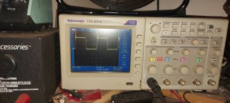
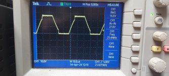
Good morning. Well, there are def some issues here. Thought maybe it was something in output section, so removed the outputs and rectifiers... cause on startup I could hear a loud "pop or click" sound from somewhere in the output section. The relays are at the end of the power supply. So not sure where it was coming from. Square wave doesn't fully form, transformer(s) squeal. Repeated over and over every time I tried to power up.
With outputs and rectifiers removed, the square wave forms... super slowly. Current starts out ok, then wave gets all this ringing at the front and current goes up fast. Like almost 10 amps in a couple seconds after wave fully forms. Probe is on the drain leg.
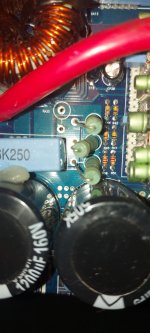
I did notice that RA35 seems to be missing. Not sure it's purpose. It seems to be in parallel with RA30, 31, 32.
With outputs and rectifiers removed, the square wave forms... super slowly. Current starts out ok, then wave gets all this ringing at the front and current goes up fast. Like almost 10 amps in a couple seconds after wave fully forms. Probe is on the drain leg.
I did notice that RA35 seems to be missing. Not sure it's purpose. It seems to be in parallel with RA30, 31, 32.
Attachments
Last edited:
Yes I used BD139/40 drivers.
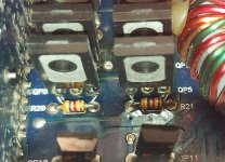
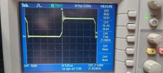
Swapped R20/21 to 1k resistors. Idle current is much better at about 2.5 amps after full duty cycle. 13v supply. It iisss slowly climbing though. About .008-0.024 amps per screen refresh.
Shall I swap the other side as well?
It still moves to full duty cycle pretty slowly. The output relays click before it's even at 80%
Without the rectifiers, the duty cycle is going to go higher than it normally would... at idle. You can swap the other two. The 494 can easily drive 500 ohms per output.
The soft-start is determined by CS9 and RS23 on the driver board. Check those if you're concerned about the time to ramp up (although it is likely OK).
The soft-start is determined by CS9 and RS23 on the driver board. Check those if you're concerned about the time to ramp up (although it is likely OK).
- Home
- General Interest
- Car Audio
- SoundStream XXX 6500 gate resistors