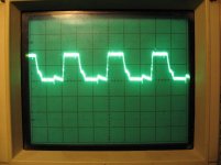
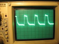
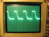
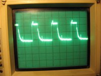
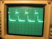
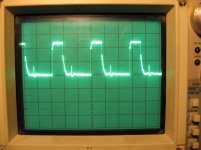
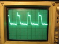
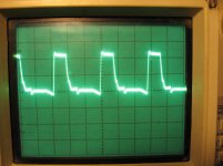
No, that was the drain signal of the fet. The first 2 here are on the gate leg of the fet. First no remote, second with remote. Then the next 2 are from pin 9 of the 494. First one without remote on big amp, second with remote on big amp.
Attachments
I added 2 330ohm 1/8 watt resistors from pins 9 and 10 to pin 7. I then replaced all 4 drivers with new ones.
When I went to power it on, now the yellow light no longer blinks and its back to protect light blinking. At first it was solid, then would try to turn on, then blink.
Solid red led is thermal... so I replaced a BCP56N next to the thermistor, and now its back to blinking protect when powered on. I even removed it from the 2ohm current limiter and just gave it a 30 amp fused source. It pulls about 1.1amps with just the small amp driving the fets. When I add remote power to the large amp, current draw goes up to around 1.5-1.6amps then falls once it goes into protect, up and down between 1.1 and 1.8ish even. This is just a fused connection, no current limiter.
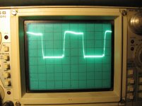
Attached are the 4 driver wave form pics again. First 2 are on the fet gate leg, first no remote to large amp, second with. There is a large spike when I add remote????. The last 2 pics are from the 494 pin 9. Third one no remote power, 4th one with remote.
When I went to power it on, now the yellow light no longer blinks and its back to protect light blinking. At first it was solid, then would try to turn on, then blink.
Solid red led is thermal... so I replaced a BCP56N next to the thermistor, and now its back to blinking protect when powered on. I even removed it from the 2ohm current limiter and just gave it a 30 amp fused source. It pulls about 1.1amps with just the small amp driving the fets. When I add remote power to the large amp, current draw goes up to around 1.5-1.6amps then falls once it goes into protect, up and down between 1.1 and 1.8ish even. This is just a fused connection, no current limiter.
Attached are the 4 driver wave form pics again. First 2 are on the fet gate leg, first no remote to large amp, second with. There is a large spike when I add remote????. The last 2 pics are from the 494 pin 9. Third one no remote power, 4th one with remote.
Attachments
I reinstalled the 4427, and powered it up. It slowly forms a perfect square wave then goes into protect. Even with no current limiter and just a fused source it pulls 3amps or so max. (this is a large amp) Pic is set to 5v/div and 10us
Should I reinstall some of the outputs, and see what happens?
Should I reinstall some of the outputs, and see what happens?
Attachments
Last edited:
Back to this one... I reinstalled the outputs. Amp still tries to powers on with no current limiter for a couple seconds, then cuts out blinks yellow 16 times then tries to power back on. Current draw is never more then 3amps after caps charge. If I let it keep cycling over and over, the rail voltage slowly climbs to over 250v. It was at 283v when I removed remote power to stop it from cycling.
I have the following readings on the output pads when the amp is on:
Low side:
G: 0.013v
C: 80.2v
E: 0.015
High Side:
G: 80.1v
C: 283v
E: 80.5v
But I'm not seeing any wave forming.
I have the following readings on the output pads when the amp is on:
Low side:
G: 0.013v
C: 80.2v
E: 0.015
High Side:
G: 80.1v
C: 283v
E: 80.5v
But I'm not seeing any wave forming.
Last edited:
No I don't... I first checked the signal between the PIC chip and the HEF4070BT (which then feeds the IR2113S). Signal looks like the short video. I then checked every pin on the pic chip and they all do the same when trying to cycle. The only 2 that are different are the 2 pins that feed the PS drivers IC.
I did note that that amp has the following readings on the output transistors before remote power was used... I just added power and ground and there was voltage on the output pads???
G: 4.4v
C: 13.03v
E: 4.4v
G: 0.0v
C: 4.4v
E: 0.0v
Should there be voltage there without remote power?
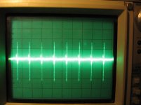
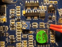
Here is a link to a short video of the wave form... its hard to capture it, cause it shows up so faint. Scope is set to 2v/div and 10us. It's the only combo I could have anything show up. Also a pic of the main part. Something has to be wrong with this amp... I did buy another PIC chip but I'm worried that it might not be factory set to SD settings. There was a sticker on it saying stuff.
http://vid1047.photobucket.com/albums/b475/deadlysones/Videos/MVI_2951_zpscsah1yfu.mp4
I did note that that amp has the following readings on the output transistors before remote power was used... I just added power and ground and there was voltage on the output pads???
G: 4.4v
C: 13.03v
E: 4.4v
G: 0.0v
C: 4.4v
E: 0.0v
Should there be voltage there without remote power?
Here is a link to a short video of the wave form... its hard to capture it, cause it shows up so faint. Scope is set to 2v/div and 10us. It's the only combo I could have anything show up. Also a pic of the main part. Something has to be wrong with this amp... I did buy another PIC chip but I'm worried that it might not be factory set to SD settings. There was a sticker on it saying stuff.
http://vid1047.photobucket.com/albums/b475/deadlysones/Videos/MVI_2951_zpscsah1yfu.mp4
Attachments
Last edited:
O.K.... well... it appears if I hold the scope probe or a volt meter on Pin 3 of the PIC16F1828 for a few seconds the amp turns on. Runs for about a minute or so, but has no output wave.
I have the following voltages on the PIC chip when amp is running.
1) 5v
2) 2.38v
3) CLK pin - 0.029 (also makes amp turn on)
4) 5v
5) 2.19v
6) 2.35v (power supply wave form)
7) 2.19v
8) 4.05v
9) 0.029v
10) 0.029v
11) 5.58v
12) 0.028v
13) 0.028v
14) 0.953v
15) 4.49v
16) 2.35v (power supply wave form)
17) 2.27v
18) 0.001v
19) 4.44v
20) 0.003v
When it kicks back out, the protection light blinks 16x then it goes back to trying to start, won't go, blinks yellow 16x over and over unless I touch pin 3 again for a few seconds, then it will power up fine again and run for a minute or 2 and go back to protect.
I see no square wave though... just a wave that looks like that above pic.
Last edited:
When you probe the CLK pin, does it kill the power supply drive pulses and make the LEDs come on as if the amp was powering up or does it start the drive pulses?
email me:
babin_perry@yahoo.com
email me:
babin_perry@yahoo.com
- Status
- This old topic is closed. If you want to reopen this topic, contact a moderator using the "Report Post" button.
- Home
- General Interest
- Car Audio
- SounDigital SD16KD-SMD