I understand that this was a general example only, but I would like to add that this can be much improved on. For example, what is shown as a CCS and left undefined, using appropriate BJTs would allow for considerably better PSU rejection. Adding a buffer transistor before the VAS trannie would very significantly reduce distorion and improve dynamic stability.
If I did it, I'd use a buffer transistor followed by a cascode for the VAS, to give it as much linearity as possible.
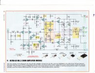
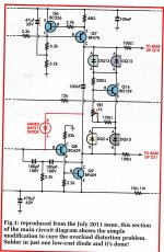
The real circuit plus a later modification to the VAS to prevent sticking under gross overload on signal input at 10 kHz. The added BAV21 diode forms a Baker clamp. Without this it takes 5-6 microseconds for the amplifier to recover to normal.
I have not build this project, however it may be of some general interest.
Attachments
Auto Union 1000S three cylinder two stroke, front wheel drive. Any ideas about this one?
What's to think? The East German Wartburg was a rip off of this Auto Union. To be sure, it goes and it goes well, even surprisingly well given that the technology is at least 50 years old. It even has a pleasant sound to it. Unfortunately, it leaves a cloud of bluish mist after it and a godawful stink.
The real circuit plus a later modification to the VAS to prevent sticking under gross overload on signal input at 10 kHz. The added BAV21 diode forms a Baker clamp. Without this it takes 5-6 microseconds for the amplifier to recover to normal.
I have not build this project, however it may be of some general interest.
Yes, that's about how I'd do it, the only difference being that instead of a Darlington VAS I'd use a cascode, a bit more complicated to implement, but in my view, with several improvements above this. But no matter, this should work just fine.
I was very pleased with the statement that rocket engines are rarely simple. I have worked with the company who made it happend circa 1943. By pure chance I know Dr Bowers who made fuel cells work in 1952. These go back to the time before electronics. My BBC friend Pippa was Alan Bonds secretary ( JPW Sonatas ). She can not remember a word of how a hybrid jet/rocket works, yikes. The big problem is ice. The condensor ( not capacitor ) must not ice up.
I prefer simple amps but don't mind complex house keeping circuits. These are the gyro's of the rocket if you like. The idea being let that signal travel as fast as possible throught the amp. The bandwidth is not the question. It is making as few copies as possible. The analogy is like old slide film. It can make a one to one copy as in films. Although a very high quality process subtle things happen. Dan says 1/f noise.
I was loooking at amps that don't need VAS caps. They always need something. I use the VAS cap to add local output stage feedback so feel it should be retained.
It is sad this man calls himself Mr Evil. None the less some good observations on long tail pairs and using a cascode. The A4 came from another Mr Evil I guess ? I drive a VW so who am I to say ?
https://mrevil.asvachin.eu/amp/topologies/rush/
Rocket engines are not too complicated in working principles, but providing for working principle conditions is a bitch.
Similar here - cascode VAS stages are fairly well known as such, but providing for the perfect operating conditions can be a bitch. In my version, for example, the cascode VAS stage needs a 100 uF capacitor to filter out the work ("lower") transistor, to rid it of possible zener noise and whatnot. In return, I can make it have an unbelievably short settling time than otherwise, even when running at larger bias currents (say, over 15 mA) which we will need if we want a wide open loop bandwidth. incidentally, most amps remembered as good 'uns did run their VAS at 13 mA and above.
Similar here - cascode VAS stages are fairly well known as such, but providing for the perfect operating conditions can be a bitch. In my version, for example, the cascode VAS stage needs a 100 uF capacitor to filter out the work ("lower") transistor, to rid it of possible zener noise and whatnot. In return, I can make it have an unbelievably short settling time than otherwise, even when running at larger bias currents (say, over 15 mA) which we will need if we want a wide open loop bandwidth. incidentally, most amps remembered as good 'uns did run their VAS at 13 mA and above.
On Nige's comment regarding Dan's belief that 1/f noise could be a problem, here's what happened to me.
A few years ago, I noticed something odd with the FM signal. Next I noticed that the bass drivers' membraned were trying to get out, quite visibly moving frnt and back. Switching on the subsonic filter (6 db/oct. @ 15 Hz) cured the problem.
We often think subsonic noise and problems happen only with LPs, because of warm and tonearm issues, but this is not true. They can happen with any input, for numerous reasons. FM goes down to 10 Hz in some places.
Besides, try the simple test if you have a subsonic filter available, listen to whatever with and without it and chances are you'll find it all sounds better with it in circuit. VERY few loudspeakers can actually faithfully reproduce much below say 30 Hz, so why not lift its burden?
Some Food For Thought....
You can't see it, you can't smell it, you can't taste it.....you can't hear it......
BUT you can hear it's higher order consequential effects if you understand what to listen for !.
Over on the JCBT thread there has been recent discussion of Richard Heyser's Audio Magazine draft unpublished articles.
Richard Feynman and Dick Heyser have a lot in common in their approaches.....no idea if they ever met.
Some pretty heavy reading and concepts presented in sensible and logical ways....kudos, rip, some of this might help you in your audio searchings.
Mr Heyser emphasises the concept of energy...energy sends, energy flows and energy returns.....that has always been my approach/view also, ever since as a young kid/novice first dabbling in electrics and electronics.
Anyway, RH is highlighting that there are all sorts of/numerous signal extraneous modulation sources in typical electronics, and that these cause higher order IMD/AM/FM like behaviours.
These behaviours are not picked up by standard FR/THD/IMD tests, BUT they are audible, and help to explain the objective/subjective dichotomy.
In my view, those who insist/stick to standard measurements only, have not learned to listen through, and hear/note/understand higher order effects.
So, in my experience/understanding there is very good argument for simpler circuitry, including zero feedback topology, more especially in the final energy delivery/transduction stages.
IME/IMHO the arguments that lower order harmonic distortions don't really matter are quite correct....the devils are higher order harmonic distortions and a bunch of differing modulation distortions.
Modulation distortions are unnatural, and what the alert readily ear objects to, ditto higher order harmonic behaviours.
NFB systems are by definition recursive....for a simple single frequency stimulus NFB systems are relatively well behaved.
When stimulated by a wideband noise type signal (complex music), NFB systems are in a sense their own worst enemy.
Dan.
Yes, imo this is a vitally important but usually not understood/not considered aspect of audio electronics....other electronics areas and other fields also.Dan says 1/f noise.
You can't see it, you can't smell it, you can't taste it.....you can't hear it......
BUT you can hear it's higher order consequential effects if you understand what to listen for !.
Over on the JCBT thread there has been recent discussion of Richard Heyser's Audio Magazine draft unpublished articles.
Richard Feynman and Dick Heyser have a lot in common in their approaches.....no idea if they ever met.
Some pretty heavy reading and concepts presented in sensible and logical ways....kudos, rip, some of this might help you in your audio searchings.
Mr Heyser emphasises the concept of energy...energy sends, energy flows and energy returns.....that has always been my approach/view also, ever since as a young kid/novice first dabbling in electrics and electronics.
Anyway, RH is highlighting that there are all sorts of/numerous signal extraneous modulation sources in typical electronics, and that these cause higher order IMD/AM/FM like behaviours.
These behaviours are not picked up by standard FR/THD/IMD tests, BUT they are audible, and help to explain the objective/subjective dichotomy.
In my view, those who insist/stick to standard measurements only, have not learned to listen through, and hear/note/understand higher order effects.
So, in my experience/understanding there is very good argument for simpler circuitry, including zero feedback topology, more especially in the final energy delivery/transduction stages.
IME/IMHO the arguments that lower order harmonic distortions don't really matter are quite correct....the devils are higher order harmonic distortions and a bunch of differing modulation distortions.
Modulation distortions are unnatural, and what the alert readily ear objects to, ditto higher order harmonic behaviours.
NFB systems are by definition recursive....for a simple single frequency stimulus NFB systems are relatively well behaved.
When stimulated by a wideband noise type signal (complex music), NFB systems are in a sense their own worst enemy.
Dan.
Last edited:

DF96 said some time ago that negative feedback doesn't create high order harmonics. I hadn't really considered it that way although had read about it. The higher harmonics dominate the picture as the feedback increased. After much testing I think I can confirm he is right. Although the amp I choose might be exactly the type that would prove that. Put as simply as possible the loop runs out of gain at the higher frequencies. The important bit was looking to find the already existing harmonics when lower feedback with about the same proportions.
Valve amps become nasty as feedback is applied. Sometimes this is not true.
MOS FET amps seeem to have a lot of higher harmonic when talking about 20 kHz. It seems like class D harmonics this can be ignored. However FET's seem very happy with negative feedback. Lessons learnt with bipolar amps are best forgotten when FET's.
One suggestion I have read is that the feedback goes arround the loop many times and this causes smearing of detail. I am sure someone will save me the trouble of doing the maths and say if true it is miniscule. This I supect was the type of distortion DF 96 strongly thought non existant.
What's to think? The East German Wartburg was a rip off of this Auto Union. To be sure, it goes and it goes well, even surprisingly well given that the technology is at least 50 years old. It even has a pleasant sound to it. Unfortunately, it leaves a cloud of bluish mist after it and a godawful stink.
DKW and was made by Saab also.
"NFB systems are by definition recursive....for a simple single frequency stimulus NFB systems are relatively well behaved.
When stimulated by a wideband noise type signal (complex music), NFB systems are in a sense their own worst enemy"
Could you expand what you mean here?
I hope you are not inferring that the amplifier signal goes "round and round"!
Cliff
When stimulated by a wideband noise type signal (complex music), NFB systems are in a sense their own worst enemy"
Could you expand what you mean here?
I hope you are not inferring that the amplifier signal goes "round and round"!
Cliff
That is true, but open to misunderstanding. Harmonics (and IM) are created by amplifier nonlinearity, not negative feedback. However, negative feedback gives the nonlinearity a chance to act on a combination of the input signal and the output signal so more high order products are produced - but then reduced by the negative feedback. You can get exactly the same effect with no feedback if a non-linear circuit element forms a potential divider with a linear circuit element; it is a matter of algebra, not feedback.nigel Pearson said:DF96 said some time ago that negative feedback doesn't create high order harmonics.
This old chestnut gets dragged out time and time again by people who don't understand electronics and maths. Audio circuits consist of (slightly) non-linear amplifiers and (slightly) non-linear filters, not genuine delays. Feedback can be regarded as instantaneous for audio purposes. If you want to worry about delayed feedback then you need to design VHF/UHF amplifiers.One suggestion I have read is that the feedback goes arround the loop many times and this causes smearing of detail. I am sure someone will save me the trouble of doing the maths and say if true it is miniscule. This I supect was the type of distortion DF 96 strongly thought non existant.
Dan, I liked your assessment of the distortion issues - however, I would not have worded the NFB aspect as above: my take is that if you are using strong NFB then make sure you get the functioning of the loop 100% right, in every area of its implementation - because, a little bit of sloppiness will certainly drag down the subjective results, possibly making that quite a bit worse than a minimal NFB solution would.NFB systems are by definition recursive....for a simple single frequency stimulus NFB systems are relatively well behaved.
When stimulated by a wideband noise type signal (complex music), NFB systems are in a sense their own worst enemy.
Dan.
Last edited:
Werner Klemperer's father Otto was a famous conductor of classical music who got out of Germany before WW2.
"NFB systems are by definition recursive....for a simple single frequency stimulus NFB systems are relatively well behaved.
When stimulated by a wideband noise type signal (complex music), NFB systems are in a sense their own worst enemy"
Could you expand what you mean here?
I hope you are not inferring that the amplifier signal goes "round and round"!
Cliff
That would be "The music goes round and round and it comes out here" a song by Kenny Ball if I remember correctly.
If you refer back to page 1752 and my message 17515 there are two attachments dealing with amplifier stability.
As mentioned in the second of these the science is due to H.W.Bode an employee of Bell Laboratories in the 1930's. Audio amplifiers have come a long way since then but the laws of physics are still the same.
A study of the attachments will give you an overview of problems with negative feedback systems and then you can ignore some of the snippets circulated on this thread.
The articles are pitched at the DIY hobbyist rather than the hard core enthusiasts. Cordell's book was suggested by D.V.V. for more detailed information.
That is true, but open to misunderstanding. Harmonics (and IM) are created by amplifier nonlinearity, not negative feedback. However, negative feedback gives the nonlinearity a chance to act on a combination of the input signal and the output signal so more high order products are produced - but then reduced by the negative feedback. You can get exactly the same effect with no feedback if a non-linear circuit element forms a potential divider with a linear circuit element; it is a matter of algebra, not feedback.
This old chestnut gets dragged out time and time again by people who don't understand electronics and maths. Audio circuits consist of (slightly) non-linear amplifiers and (slightly) non-linear filters, not genuine delays. Feedback can be regarded as instantaneous for audio purposes. If you want to worry about delayed feedback then you need to design VHF/UHF amplifiers.
DF, a hypothetical question. In your view, which of these two amps has a better chance at sounding better. Amp A has an OL bandwidth of say 10 kHz and uses say 40 dB of GNFB to obtain a THD figure of say 0.008% at full power into 4 Ohms, 20-20.000 HZ, or Amp B which has an OL bandwidth of say 100 kHz, uses just 20 dB of GNFB to obtain a THD figure of 0.03% at full blast same as A under the same conditions.
And what is, in your view, the lowest THD number we could agree on is below the threshold of human hearing. Just your opinion. Ditto for IM.
Werner Klemperer's father Otto was a famous conductor of classical music who got out of Germany before WW2.
The old boss of Thorens also. Mr Leitner.
Just so that my above questions are not understood as any sort of provocation, the one thing I have noticed on this forum, at least in the two threads I follow, is that people throw about numbers like they were for free. Some claimed that they can hear differences down to well below 0.01% THD, which I strongly doubt, although I recognize that only the THD percentage tells half the story, the other half being the harmonic decay. If it decreases relatively linearily, say 2nd harmonic 0.03%, 3rd say 0.02% and so forth, and say 7th is at 0.08%, that will be one thing, another would be if 2nd harmonic is at 0.01%, but 7th is as 0.03%, which is NOT what I expect to see in a competent designs.
Also, quoting average specs hides what the peaks are, and it has happened that PEAK harmonc distortion of higher harmonics did rise well above the spec on a peak basis, but did fit into the average figure. The resultimg sound was brittle despite nominally good specs. And remember, general specs provided by manufacturers ALWAYS show the average, NEVER peak, NEVER a spectrum.
Also, quoting average specs hides what the peaks are, and it has happened that PEAK harmonc distortion of higher harmonics did rise well above the spec on a peak basis, but did fit into the average figure. The resultimg sound was brittle despite nominally good specs. And remember, general specs provided by manufacturers ALWAYS show the average, NEVER peak, NEVER a spectrum.
It is possible to make zero feedback amplifers that have good specs. I almost ( no loop, no local ) did exaclty that with a pentode and output triode ( it has internal feedback ). Both had capacitor bootstrapping of the cathode resistor. There was some positive feedback that wasn't really required. The distorion 0.2% all second harmonic at 1 watt and 1% at 5 watts . The output maintained up to 8 watts if KT88. Unlike any amp I have heard including the most expensive 300 B types the reality was very high. It was very happy with Quad ESL63's. This technique is called pre distortion by some. I have a very large bucket of valves. The way the pentode is set up allows almost dead ones to work. The distortion will be 1.5% worst case and no change in trends. The output valve is cheap so can be changed when thought to be it's time. It is a SE design so no PP matching. Mostly I don't like big PP valve designs. I sort of like the Dynaco. One thing I notice is that valve amps can produce very ugly distorion at a drop of a hat. It also sounds ugly. To my surprise I like UL feedback. I suspect UL and loop are not happy bed fellows. I use 82% UL ( almost triode ). This seems to give 30 % improvement in sensetivity for no great change in spec. It looks better if honest. I have seen a diode put on the UL to g2 link. I was strongly warned not to do this. I suspect in SE it is fine, in PP it could show very high voltages ? The suggestion being the speaker could inject back EMF as the reason to do it. Now that's very interesting. The Russian guy said the results could be heard but not measured. This is possibly so. If a music test could be devised perhaps we could? That is to re-digitise music and do percentage of error. It would be of no use to quote. It would be useful for trends. The guy was happy to use 1N4007. A TV engineer warned that a voltage multiplier might be formed. I use EL 34 at 450V. It might stand some abuse.
The amp accepted loop feedback very well. I had no interest in that as the quest was high gain. 620 mV in 8 V out. Both distortion and sensetivity was above typical designs. 5% THD is what people never admit to. Then 2 V to drive. That is an amplifer of no value. I was able to better the lumped THD spec. I decided not to as I like the Hiraga prefered harmonics ( suspension bridge curve ).
I made a PP version with SE input. That is the outputs looking like a long tail pair. This required 56 V of drive. This worked best as all triode. It was almost impossible to make it's advantages count except the PSU was less complex. The point was to drive some 211 I have been offered, 56 V rms should be enough .
BTW. Very real means layers inside layers. Stereo inside sterero. That is switch one speaker off and hear almost it's own version of stereo. Dire Straits Six Blade Knife for example. Suddenly all the people were in their own space. This was on very cheap speakers even ( Mission 760 ).
I was listening to my OB speakers. Many times they are junk.Then I play some 1930's or 50's music and they are magic. Someone not just in the room but with size and shape a blind person might know as real life. The feeeling is that for obvious reasons modern mixing is rather poor. The reason being they use speakers for mixing not unlike > 6000 000 000 use, they have to if they want sales. The speakers until my tweeters arrive only have 8 kHz. I can get 10 kHz with EQ, more if I want quantity rather than quality. The surprising thing is modern music has no treble. It has somthing different. I don't know what is has but it isn't music, musical salt rather than taste. Spendor BC1 showed the same things. It gave me a little more. The Spendor can sound dreadful. It is not a diplomatic speaker although polite ( yes ).
I was listening to my OB speakers. Many times they are junk.Then I play some 1930's or 50's music and they are magic. Someone not just in the room but with size and shape a blind person might know as real life. The feeeling is that for obvious reasons modern mixing is rather poor. The reason being they use speakers for mixing not unlike > 6000 000 000 use, they have to if they want sales. The speakers until my tweeters arrive only have 8 kHz. I can get 10 kHz with EQ, more if I want quantity rather than quality. The surprising thing is modern music has no treble. It has somthing different. I don't know what is has but it isn't music, musical salt rather than taste. Spendor BC1 showed the same things. It gave me a little more. The Spendor can sound dreadful. It is not a diplomatic speaker although polite ( yes ).
- Status
- Not open for further replies.
- Home
- Member Areas
- The Lounge
- Sound Quality Vs. Measurements