Input capacitance seems to be different between the N and P channel. More on the original Hitachi than the Exicon. Their turn on and turn off times vary too. Exicons being better in all of these specs and closer N to P, but not the same. I feel I should be adjusting something, Like R21
I am only dipping in and out of here, but I really do recommend you back off and read some basic theory! You CANNOT understand a circuit by picking out unconnected bits from a component datasheet!
For example:
Input capacitance here will have no effect except at high Rf frequencies.
Ton / Toff are only relevant to switching circuits. They mean nothing in linear applications such as this. The Fets are not switched!
Input capacitance seems to be different between the N and P channel. More on the original Hitachi than the Exicon. Their turn on and turn off times vary too. Exicons being better in all of these specs and closer N to P, but not the same. I feel I should be adjusting something, Like R21
For example:
Input capacitance here will have no effect except at high Rf frequencies.
Ton / Toff are only relevant to switching circuits. They mean nothing in linear applications such as this. The Fets are not switched!
In and out of all my books, this is not discussed. I noticed the difference in the schematic. I know devices are not truly complementary, so I was looking for differences. Q10 and Q11 need only to supply sufficient current to swamp the gate cap. So, if this is not relevant at AF, then why the very large difference between R18 at 470 Ohms and R21 at 68? I do not see this n Cordell or any of the other schematics I have. I suspect something important here as the voltages supplied in the manual have a .2V offset between the gates and ground. I am sure he had a reason.
Another detail I don't understand. Function of R15 and R19. If they were tubes, I would say grid isolation resistors. What are they doing in BJTs?
As I am replacing the Hitachis with the Exicons, I would prefer if they behaved. They are not cheap and a 2 week lead time.
Another detail I don't understand. Function of R15 and R19. If they were tubes, I would say grid isolation resistors. What are they doing in BJTs?
As I am replacing the Hitachis with the Exicons, I would prefer if they behaved. They are not cheap and a 2 week lead time.
Potential alternate L-MOSFET supplier. Never heard of them before.
Magnatec. ALFET Lateral MOSFETs
Magnatec. ALFET Lateral MOSFETs
IMHO That's one good reason for R18 and R21 to be different. Those resistors and input capacitances form low pass filters, with delay. You need the top and bottom halves of the waveform to have equal delay.Input capacitance seems to be different between the N and P channel.... Their turn on and turn off times vary too.
The existence of P2 is a mystery to me. Hopefully it's not to adjust DC offset; that'd be about the worst possible way to do it. Maybe it's to adjust for symmetrical slew rate limiting? Whatever it's purpose, it seems silly to allow VAS idling current to be adjusted over a 50-to-1 range. Maybe there's a typo in the schematic and it's supposed to be 50R, not 500R, or maybe there's another smaller resistor connected in parallel to it?Position of P2...
That extra 0.22R resistor may not be a mistake, but the 2k2 in series with the output is definitely a typo. BTW, that circuit's totally different to the RA840 BX4 (see below). I wonder what flavor you have? Labels aside, there's often something in the fine print about "subject to change without notice".RA 840BX..... Like .22 Ohms on each output emitter, but another .22 ohms on the input to the output network.
Attachments
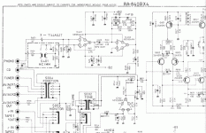
Same function as grid stoppers; they're for stability. Same goes for R18 and R21. When thinking about R18 and R21, bear in mind there's no DC voltage across them. That 0.2V difference in Vgs is irrelevant.Another detail I don't understand. Function of R15 and R19. If they were tubes, I would say grid isolation resistors. What are they doing in BJTs?
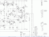
Wow, sure is different. I think I have seen that exact configuration in one of the no-name schematics I copied down.
Using the ALFET application guide on the, the -3dB on the original Hitachis were 2.6M for the P and 546K for the N. With the Exicon numbers at the recommended 1Mhz, the resistors would be 330 and 220 plus or minus a little. This does not take into account a difference in output impedance between Q10 and Q11. Guide of course said nothing about that.
Using the ALFET application guide on the, the -3dB on the original Hitachis were 2.6M for the P and 546K for the N. With the Exicon numbers at the recommended 1Mhz, the resistors would be 330 and 220 plus or minus a little. This does not take into account a difference in output impedance between Q10 and Q11. Guide of course said nothing about that.
R 15 and 19 are not as close on the board as one might suggest then. Maybe a simple place for improvement.
Here is what I found on the R21 question
http://products.semelab-tt.com/pdf/ApplicationNoteAlfet.pdf
Here is what I found on the R21 question
http://products.semelab-tt.com/pdf/ApplicationNoteAlfet.pdf
See if it uploaded this time
This looks like a typical amateur design.
Hi tvrgeek,
Thank you for the link. I haven't read much on the newer power mosfets, or even Nelson's power J-Fets. This, I will read (printing it off now).
The very best way to learn from written material is to grab application notes and other material from various manufacturers. That stuff is a gold mine, even down to the stone age basics - like how tight do I crank the mounting screws down. That is extremely important. On Semi also has a ton of information available. Read even the old ones you think don't apply anymore. They often do.
Hi a.wayne,
If you think the sound was bad, you should see how they were built. Yuk! Sadly, Bryston is not alone in the "looks like it was made by monkeys" department.
The tube amp I really like so far? A couple, an Eico HF-87 that I rebuilt (for me") ) and a home built 20 wpc amplifier (using 7581A outputs - bigger 6L6GC) that was designed and built in consultation with Fred Hammond - the man. I got that with the letters on a trade for work done. This fellow did an amazingly good job. The Eico HF-81 sounds really good, and I have an Eico ST-70 I'm looking forward to rebuilding some time. Another item for us to enjoy. That one uses 7591A outputs though.
) and a home built 20 wpc amplifier (using 7581A outputs - bigger 6L6GC) that was designed and built in consultation with Fred Hammond - the man. I got that with the letters on a trade for work done. This fellow did an amazingly good job. The Eico HF-81 sounds really good, and I have an Eico ST-70 I'm looking forward to rebuilding some time. Another item for us to enjoy. That one uses 7591A outputs though.
-Chris
Thank you for the link. I haven't read much on the newer power mosfets, or even Nelson's power J-Fets. This, I will read (printing it off now).
The very best way to learn from written material is to grab application notes and other material from various manufacturers. That stuff is a gold mine, even down to the stone age basics - like how tight do I crank the mounting screws down. That is extremely important. On Semi also has a ton of information available. Read even the old ones you think don't apply anymore. They often do.
Hi a.wayne,
If you think the sound was bad, you should see how they were built. Yuk! Sadly, Bryston is not alone in the "looks like it was made by monkeys" department.
Well, I was authorized warranty for McIntosh. To be honest with you, their new stuff sounded really good compared to their older designs. I rebuilt a pair of MC40 amplifiers for myself. I used every sure-fire trick I knew of. Matching resistors and changing capacitor types. When I sparked them up, they worked fine. Nice and quiet, lot's of punch. They sounded cold, sterile. I was so disillusioned that I sold the pair cheap, about $1K for the pair - no new tubes. The best sounding tube McIntosh amps I have worked on were the MC240 and MC275. I would have liked an MC240. Anyway, you have to remember that these are class B designs with a special unity coupled output transformer.Mcintosh , only their tube stuff worked for me
The tube amp I really like so far? A couple, an Eico HF-87 that I rebuilt (for me
) and a home built 20 wpc amplifier (using 7581A outputs - bigger 6L6GC) that was designed and built in consultation with Fred Hammond - the man. I got that with the letters on a trade for work done. This fellow did an amazingly good job. The Eico HF-81 sounds really good, and I have an Eico ST-70 I'm looking forward to rebuilding some time. Another item for us to enjoy. That one uses 7591A outputs though.I don't know. I'd have to disagree from what I've heard on my bench. The new McIntosh stuff is well worth a listen. If nothing else, they are reliable. That and there are no shortages of tube products that do not sound very good out there.The MC3500's were no slouch , special really, last great MAC, IMO ....
-Chris
Hi Anatoliy,
Except it isn't typical at all. It uses a CCS for tail current and the Vas is loaded with a CCS, not a bootstrap that is so common. What it is, is common for a production amplifier. Some amplifier designs seen here (done by amateurs) are far more inspired, so I take your point is this was your reference.
-Chris
Are you surprised?This looks like a typical amateur design.
Except it isn't typical at all. It uses a CCS for tail current and the Vas is loaded with a CCS, not a bootstrap that is so common. What it is, is common for a production amplifier. Some amplifier designs seen here (done by amateurs) are far more inspired, so I take your point is this was your reference.
-Chris
Hi,
Probably right for the Mosfets. You cannot "overbias" lateral fets.
Yes, I got appx. that value looking at the schematic. It is probably adequate.
The input and reverse transfer capacitances between the P-Channel and N-Channel vary around 1.5 : 1. That's why. The values are common for these mosfets.
Bad copy, drawing I suspect. Traditional R18 should be 680R and R21 470R. This is what is commonly used with Hitachi fets and also works normally with the 2nd source parts.
Given that one pair of Fet's is really, really marginal for such an Amp I would suggest try switching to the double die Parts with twice the current rating if you replace them and halve the gate stopper values.
I am not sure what "grid isolation resistors" are supposed to be.
Gate stoppers are there to reduce the Q of parasitic tank circuits in the grid circuits of tubes, they work the same for Fet's (where they are called Gate stoppers) and BJT's (where they are called Base Stoppers). Job in each situation, reduce the risk of parasitic oscillation.
Ciao T
Trying to understand the bias in the DH 120. I noticed both channels P1 is set to zero. Maximum bias. Glypt from the factory.
Probably right for the Mosfets. You cannot "overbias" lateral fets.
Position of P2 suggests the Q9 only carries about 2.5 mA.
Yes, I got appx. that value looking at the schematic. It is probably adequate.
Not sure why R18 and R21 are different. Is this based on the difference in dc offset of .2V and the charge rate of the gate capacitance?
The input and reverse transfer capacitances between the P-Channel and N-Channel vary around 1.5 : 1. That's why. The values are common for these mosfets.
In and out of all my books, this is not discussed. I noticed the difference in the schematic. I know devices are not truly complementary, so I was looking for differences. Q10 and Q11 need only to supply sufficient current to swamp the gate cap. So, if this is not relevant at AF, then why the very large difference between R18 at 470 Ohms and R21 at 68?
Bad copy, drawing I suspect. Traditional R18 should be 680R and R21 470R. This is what is commonly used with Hitachi fets and also works normally with the 2nd source parts.
Given that one pair of Fet's is really, really marginal for such an Amp I would suggest try switching to the double die Parts with twice the current rating if you replace them and halve the gate stopper values.
Another detail I don't understand. Function of R15 and R19. If they were tubes, I would say grid isolation resistors. What are they doing in BJTs?
I am not sure what "grid isolation resistors" are supposed to be.
Gate stoppers are there to reduce the Q of parasitic tank circuits in the grid circuits of tubes, they work the same for Fet's (where they are called Gate stoppers) and BJT's (where they are called Base Stoppers). Job in each situation, reduce the risk of parasitic oscillation.
Ciao T
Hi,
I cannot quite read the number, but that is the position and it is 33K Value.
For the DH-120 incidentally it is R11 (+ C3) which pretty much determine open loop gain and bandwidth.
I'd estimate the DC open loop gain at around 70dB and the open loop bandwidth at around 22KHz, which is not so shabby at all, given the age of the design and the pedestrian parts used.
Personally I would be tempted as said to add J-Fet buffers on the input or switch to J-Fet Inputs and increase degeneration of the VAS (Voltage Amplification Stage) and IPS/ICM (InPut Stage/Input Current Mirror).
Changing the inputs to J-Fets would be the easier choice as it requires minimal changes on the PCB. A 2SK389/LSK389 with 39V zenners in the drain leads would do well, giving around +/-0.8V linear input range without degeneration.
The VAS could also use a NPN Emitter Follower to increase the input impedance, which can offset some of the gain lost by extra degeneration.
Bod Cordell actually covers all this quite well in his book. He uses in general 1:10 degeneration.
For the DH-120 VAS this would mean around 100 Ohm Emitter resistor (change C8 to 270nF), for the input stage 510 Ohm per emitter (330 Ohm per source if J-Fets are used).
With the increased degeneration of the VAS we can drop some more voltage in ICM, so 330 Ohm degeneration there would be quite all-right.
Due to all the various changes in the circuit (mainly increase input impedance of the VAS and increased ICM impedance of the ICM due to degeneration) massively increasing degeneration actually only looses us a a few dB of OLG, which should be around 65dB.
You could probably reduce C3 then by around the loss of open loop gain, so if (to be safe) we only reduce it to 220pF we get around 65dB DC open loop gain with a -3dB point open loop of around 33KHz...
Together with the new Dual Die Exicon Mosfets and some passive parts upgrades the rebuild Amp could be quite nice.
BTW, consider changing the 2N5550 for 2SC2240BL and the 2N5401 for 2SA970BL. Whilese these transistors are not "magic", they do offer better beta linearity, lower parasitic capacitance and quite favourable Early-Effect behaviour for the job.
For the drivers (Q10/11) something akin to a pair of BF469/BF470 (which are long discontinued) might be a good choice.
Ciao T
That is the R 632, Collector of VAS to ground?
I cannot quite read the number, but that is the position and it is 33K Value.
For the DH-120 incidentally it is R11 (+ C3) which pretty much determine open loop gain and bandwidth.
I'd estimate the DC open loop gain at around 70dB and the open loop bandwidth at around 22KHz, which is not so shabby at all, given the age of the design and the pedestrian parts used.
Personally I would be tempted as said to add J-Fet buffers on the input or switch to J-Fet Inputs and increase degeneration of the VAS (Voltage Amplification Stage) and IPS/ICM (InPut Stage/Input Current Mirror).
Changing the inputs to J-Fets would be the easier choice as it requires minimal changes on the PCB. A 2SK389/LSK389 with 39V zenners in the drain leads would do well, giving around +/-0.8V linear input range without degeneration.
The VAS could also use a NPN Emitter Follower to increase the input impedance, which can offset some of the gain lost by extra degeneration.
Bod Cordell actually covers all this quite well in his book. He uses in general 1:10 degeneration.
For the DH-120 VAS this would mean around 100 Ohm Emitter resistor (change C8 to 270nF), for the input stage 510 Ohm per emitter (330 Ohm per source if J-Fets are used).
With the increased degeneration of the VAS we can drop some more voltage in ICM, so 330 Ohm degeneration there would be quite all-right.
Due to all the various changes in the circuit (mainly increase input impedance of the VAS and increased ICM impedance of the ICM due to degeneration) massively increasing degeneration actually only looses us a a few dB of OLG, which should be around 65dB.
You could probably reduce C3 then by around the loss of open loop gain, so if (to be safe) we only reduce it to 220pF we get around 65dB DC open loop gain with a -3dB point open loop of around 33KHz...
Together with the new Dual Die Exicon Mosfets and some passive parts upgrades the rebuild Amp could be quite nice.
BTW, consider changing the 2N5550 for 2SC2240BL and the 2N5401 for 2SA970BL. Whilese these transistors are not "magic", they do offer better beta linearity, lower parasitic capacitance and quite favourable Early-Effect behaviour for the job.
For the drivers (Q10/11) something akin to a pair of BF469/BF470 (which are long discontinued) might be a good choice.
Ciao T
Except it isn't typical at all. It uses a CCS for tail current and the Vas is loaded with a CCS, not a bootstrap that is so common. What it is, is common for a production amplifier. Some amplifier designs seen here (done by amateurs) are far more inspired, so I take your point is this was your reference.
-Chris
It s even less typical when looking at further this schematic..
The NFB sampling point is taken after the output fuse wich is
in serial with a resistor mistakenly marked 22K , surely 0.22R.
Then another 0.22R is in serial with the output inductance
that has no paraleled resistor, after wich is connected the zobel network....
A typo in the schematic makes even more sense. Reviewing the two updates to EB's 1982 60W design in Audio Amateur, (2-85 and 1-94) moving these resistors right to the gate would be a good idea. I notice by the DC100 article in 1984, he uses the spec sheet values. The readers' suggestions on stability are worth reading. They are making a lot more sense on why, not "do this". So using the recommendations in the app guide, I will pick new values and fly them right off the gate socket pin. Then use the AA 1-94 piece by E. Aho to see the results.
Again much thanks for the ideas. A lot to study. I am getting close on paper, so I wait for my repair parts to translate book to bench. Repair, then mod, and compare. With the part substitution recommendations, that gives me something to compare datasheet graphs so I can find what John is trying to lead me to.
I mentioned to Rod Elliot my poor On-Semi parts as he posts a list of known counterfeit parts. He said he had not had difficulty with On-Semi and offered to take a look at a couple of them. I will take him up on that. I suspect seconds sold as first. When I was in failure analysis, we found almost zero actual defective parts. Miss-used, miss-handled, but the foundries knew exactly what they built.
- Status
- Not open for further replies.
- Home
- Member Areas
- The Lounge
- Sound Quality Vs. Measurements