You want a photograph of the tape measure or what?
A link to a measurement of the difference, after the sound has entered the microphone.
If there is none, then it's an example of when sound is sometimes heard and not measured.
I'm referring to how we can differentiate size mono-aurally, not stereo time difference localization.
You want to play hopscotch in a mine field?
We cannot yet define good sound by measurement for the electronics only, and you want to bring in the speakers, which are electro-mechanical devices, as transducers are?
Actually I am wondering if we can reliably identify the difference between electrostatic, isodynamic and dynamic drivers via the measurement data.
A photo of the driver type doesn't count naturally.
A video of the air movement is most likely the answer imho, however then we have to make the air very smoky, coloured or radioactive so we can view it.
Dvv, if we take the view that amplifiers and transducers are "little instruments", which may exhibit their own sound, then that is a mine field.
If we take the view of invisibility, then vanishingly low THD, IMD and the most accurate speed seem like the most accurate tools we use to arrive at the sound quality, if we define quality as invisibility.
If an active studio speaker only advertises it's frequency response, in my eyes that's hype.
After all, what can the flat frequency response of an op-amp tell us?
Last edited:
Yes, for example I've always suspected that the electrolytics in the amplifier's power supply, which are in series with the output devices, have a substantial effect on the sound. Maybe a dynamic shunt regulator for the output stage (that didn't waste too much power at low levels) would improve the sound quality enough to be worthwhile.
I say your suspicions are spot on.
The problem with any electronic voltage regulator is essentially speed. For it not to become a bottleneck you need a regaulator which is, at the very worst, as fast as the amp, and preferably faster. If not, it may choke the amp.
This is not to big a problem for low current electronics, like preamps, tuners, etc, but in case of power amps, we are dealing with possible tens of amperes of current AND at a voltage which must not vary. Now, that IS a tall order.
To be sure, it can be done, and has been done, but in the end, you invariably end up with a complete power amplifier. NAIM is a good example - their voltage reg was about as complex as their audio electronics proper, input diff pair, 1 transistor VAS, 1 driver, 1 output device, same as their amp. And the controversy about "the NAIM sound" is still raging. Some hate it, others swear by it. Your call.
My experience tells me the best chance of getting it right is to use a single fast transistor, in my case Motorola/ON Semi MJE 15030/15031, in what amounts to a capacitance multiplier with an added, heavily filtered zener diode to the base. The transistors are effectively 60 MHz devices, capable of 8 Amps of current if pushed, and with a dissipation of 50W they are hardčy stressed by around 50-60 mA at say +/- 61V worst case. This drives a filter bank, consisting of a 2,200 uF cap, 3.3 uF cap and a 100 nF WIMA MKT cap. Technics had something like that and called it a "Virtual Battery", so the name stuck. IRF MOSFETs are a good alternative (e.g. 510/9510).
Being fatalistic, you can assume noise will also be picked up along the way, so sprinkiling some 10 uF and 100 nF caps along the way betwenn stages is never a bad idea. Costs more, yes, but it does its bit.
For the main bank of caps supporting the current stages, I stick to two rules. One is to use two 10,000 uF caps in parallel rather than one 22,000 uF cap; look up any manufacturer of caps and you'll see that two in parallel will always have a lower output impedance and a bit more current than one biggie. The other is to stick them as close to the output devices as you possibly can, which is obvious but not done very often, and certainly not often enough.
Again, following the main caps in parallel I put in 1 100 uF, 1 3.3 uF, one 100 nF cap and 1 Ohm in series with 220 nF to the ground. The idea is to get rid of as much leftover inductance of the big caps as possible. Therefore, the value of the cap after the resistor will depend on which caps and how many of them you use. For example, for my beloved two Fisher & Tausche 10,000 uF/63V the value of C is 220 nF (WIMA MKT), but for other bigga caps, it will be something else.
Dvv, if we take the view that amplifiers and transducers are "little instruments", which may exhibit their own sound, then that is a mine field.
If we take the view of invisibility, then vanishingly low THD, IMD and the most accurate speed seem like the most accurate tools we use to arrive at the sound quality, if we define quality as invisibility.
If an active studio speaker only advertises it's frequency response, in my eyes that's hype.
After all, what can the flat frequency response of an op-amp tell us?
I DO take the view that amps and speakers will each have their own sound. Ideally, they should not, or, if they really must, their contribution should be as low as possible,
I DO NOT think that vanishigly low THD, IM at al. is really essential to the sound in absolute terms so long as it's all below 0.1% worst case, but I DO believe that the decay rate of the harmonics can tell us much of the story, though not all of it.
I definitely DO believe that the regularity of the speaker's frequency response is essential however you look at it. The standard industry +/- 3 db spec is far too loose for my taste, as it allows them to have as much as + or - 6 dB of variance. Use a graphic equalizer to add or subtract 6 dB for your speaker and tell me you can't hear it. Yet, you would still be within your specs.
I believe in it so much that I spent literally months with a friend developing my own current speakers to the point where they would do 40-18,000 Hz +/- 1,5 dB at 102 dB SPL at 1 m. That is the limit of very good professional tape machines at 0 dB VU. If I use industry standards of +/-3 dB, the response would be 36-22,000 Hz.
Then we used up another few months ironing out the crossover network. All told, it took us just under a year to get it just right, although I must add we didn't decidate entire workk days to it, after all, we had to earn our normal income.
The end result is a speaker which, given a good amp, will disappear, meaning you are not hearing the sound from a box with 3 drivers, the sound is there in the air, outside the boxes. How good depends on what's producing it.
It is, of course, not perfect, but it comes damn close for me. For the money and in view of what it needs (that I know of), it's fantastic. To get that sort of sound from a shop, I would need speakers costing five figures, be it $ or €. And my bottom line was €1,200 in 2002, although this is really a false figure, as it doesn't include the real world cost of our research and work. But that was its official sale price.
Lastly, your comparison of the frequency response of a loudspeaker and an op amp is not valid. Getting a flat response from a speaker with minimum penalties elsewhere is incomparably more complex and difficult than doing the same with an op amp. Besides, an op amp may be perfectly linear, but for you to have any use of it still reequires a speaker, which may well ruin that.
Yes, for example I've always suspected that the electrolytics in the amplifier's power supply, which are in series with the output devices, have a substantial effect on the sound.
Electrolytics in the PS in series with your output devices would not let any current go through and blissful silence would be the result. I prefer silence to nonsense myself.
Nice story DVV, I hope you enjoy the fruits of your labour and made some decent profit as well.
I don't think any equalizer can completely remove the sound of a speaker driver.
If op-amp's sound different due to 0.01 versus 0.001 percent THD and 1500 ns versus 500 ns settling time, I can only imagine that speaker drivers must follow these rules as well.
If I listen with an Etymotic ER-4 with I think 0.5% THD and settling time in the milliseconds, not nanoseconds, you could say the masking effect takes place, in theory, but in reality it doesn't.
How to separate reality from illusion, well, that is the question.
We can touch reality with our fingers, glass feels like glass and sand feels like sand, no placebo effect there. I guess the debate is simply how fine a friction of sand can we feel? At that point, "common sense" starts to kick in and says only 2000 DPI of sand is perceivable, 3000 DPI is too fine, or if we can feel 3000 DPI it's "less important", I tend to think the finest DPI is precisely what is important, after a while our neural networks get used to it and don't like returning to 2000 DPI.
Just making up numbers here.
Neuroplasticity is the key here, we adjust to reality, any kind of reality, no question! We can even learn how to echolocate like bats --if we really want to--, even though it doesn't exist in our DNA. Audio perception should follow similar rules, eventually we can echolocate room acoustics for instance quite easily. I'm not saying I'm special, everyone is, sonic memory of random noise and patterns is weeks, not seconds, this is the truth.
Last edited:
Nice story DVV, I hope you enjoy the fruits of your labour and made some decent profit as well.
I don't think any equalizer can completely remove the sound of a speaker driver.
If op-amp's sound different due to 0.01 versus 0.001 percent THD and 1500 ns versus 500 ns settling time, I can only imagine that speaker drivers must follow these rules as well.
If I listen with an Etymotic ER-4 with I think 0.5% THD and settling time in the milliseconds, not nanoseconds, you could say the masking effect takes place, in theory, but in reality it doesn't.
How to separate reality from illusion, well, that is the question.
We can touch reality with our fingers, glass feels like glass and sand feels like sand, no placebo effect there. I guess the debate is simply how fine a friction of sand can we feel? At that point, "common sense" starts to kick in and says only 2000 DPI of sand is perceivable, 3000 DPI is too fine, or if we can feel 3000 DPI it's "less important", I tend to think the finest DPI is precisely what is important, after a while our neural networks get used to it and don't like returning to 2000 DPI.
Just making up numbers here.
Neuroplasticity is the key here, we adjust to reality, any kind of reality, no question! We can even learn how to echolocate like bats --if we really want to--, even though it doesn't exist in our DNA. Audio perception should follow similar rules, eventually we can echolocate room acoustics for instance quite easily. I'm not saying I'm special, everyone is, sonic memory of random noise and patterns is weeks, not seconds, this is the truth.
Kastor, I did it for myself, for my own use, and because the man who did much of the development is a good friend of mine. He was the co-owner of a speaker manufacturing company, not I, I never regarded it as a business proposition and never expected to make any money from it. I stuck firmly to what my own company did, nothing else, which are power line filters and headphone amps/preamps (if only two inputs was enough).
The other guy is the kind of friend I'd walk on fire for. I also helped him out in video editing, he is an avid scuba diver who has won the Grand Prix for amateur underwatr photography three time in the row. You see what I'm getting at: we were even then past the give-take relationship, we were and still are firends for keeps. That kind of relationship is very rare, I have just one more man I'm that tight with. Like brothers, you might say.
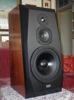
And that speaker took off, too. Exports started, he had people actually driving down from Belgium to take their speakers. Unfortunately, his business partner had a near fatal motorcycle accident, which left him completely paralyzed except for his little finger on his left hand. Things went south from there, and the company was soon dissolved. That's why I cannot put a link to it.
All I can do is show you its portrait.
Attachments
An interesting observation: some of the lounge threads here give good, factual information, while many of the so-called tech threads have all the BS.
Maybe we should swap the area names ?
Jan

You spoke too soon.

So some folks can measure it but claim it's not audible, while others can hear it but claim it's not measurable?
I think what people forget is what we measure with has to be at least 20 dB better than what we are measuring. I have this problem time and time again. I have learned how to see through that and still find the trends.
I recently built some simple speakers that seemed very accommodating. One could almost overlook the obvious frequency response problems. Correcting it actively was enough to make them very good.
Then the nightmare to solve it with coils and capacitors. The result is a poor second and very different in it's acceptance of amplifiers. Now I call that learning. I don't think the measuring helped much. Things that measured good sounded poor. Things that measure poor sounded good. Some things measure and sound good. 1 metre on axis is not a great test.
Dejan. I am a light sleeper. BBC world service seems to get me back to sleep. Poland is having a battle with Russia over exports. Poland has too many apples. Cider time in Poland I think. My company is Swiss. I hope that might help as >10% of my wage comes from Russia.
I have been building with comparators this week, it is for Russia. What a joy binary is. Uses of hysteresis to make it so. My training as an audio engineer helped as I used all positive comparators and an analogue inverter to make a window comparator. I used LM324 as it is superb for this. It both sources and sinks current whilst LM339 can only sink. It also can offer slightly more current ( 15 or 20 mA ). I needed that as my use is 18 V 18 mA . So the worlds worst op amp makes a fantastic comparator, it looks like one inside. At 20 mA 19V it will nearly swing rail to rail . The switching is with 0.5% hysteresis with is excellent. Any less and a serious fire risk. A competitor product uses a micro computer. That seems a disadvantage. In fact I am using the op amp as a computer which was the original use ( H C Lin circa 1960 US military).
You spoke too soon.
Yes I noticed, to my chagrin....
But still better than being killed by a cork. Slightly.
Electrolytics in the PS in series with your output devices would not let any current go through and blissful silence would be the result. I prefer silence to nonsense myself.
Trace out the current paths, or put a current probe on the cap's connections.
This will convince you. Where else would the load current be able to go? It has to travel a complete loop.
Trace out the current paths, or put a current probe on the cap's connections.
This will convince you. Where else would the load current be able to go? It has to travel a complete loop.
Can you make a simple drawing please that shows in what way electrolytics in the ps are in series with the output devices and where to make these measurements?
Maybe (like JC does on his preamps), a high current capacitance multiplier?
Is this really worth while ...?
I can't see how a capacitance multiplier helps when the noise we want to minimize is load-induced. They work great for filtering line noise though.
So the purpose ? Load induced noise is where it's at, line noise can be controlled and is not always present ..
I say your suspicions are spot on.
The problem with any electronic voltage regulator is essentially speed. For it not to become a bottleneck you need a regaulator which is, at the very worst, as fast as the amp, and preferably faster. If not, it may choke the amp.
This is not to big a problem for low current electronics, like preamps, tuners, etc, but in case of power amps, we are dealing with possible tens of amperes of current AND at a voltage which must not vary. Now, that IS a tall order.
To be sure, it can be done, and has been done, but in the end, you invariably end up with a complete power amplifier.
Yes, the shunt regulator would have to be somewhat better than the amplifier itself, or it might not be worth bothering with.
Can you make a simple drawing please that shows in what way electrolytics in the ps are in series with the output devices and where to make these measurements?
I'm away from my scanner today, but try this: get pretty much any transistor amplifier schematic.
Start at the output load terminal, then go to the emitter of one of the output transistors, go through it to its collector, and then we need to go to the load ground terminal to make a complete current loop. The only path available is through the power supply capacitor.
This is the reason why large capacitors are necessary for the power supply. The low frequency impedance must be low enough (the capacitance large enough) so that bass frequency currents can flow through with little impedance compared to the load. In most amplifiers they also serve to store the energy necessary to actually drive the load. To do this they are fed current pulses from rectifier diodes connected to an AC source. These pulses charge the caps quickly, usually at a rate of 120 times a second, and don't otherwise interfere much with the operation of the circuit.
Can you make a simple drawing please that shows in what way electrolytics in the ps are in series with the output devices and where to make these measurements?
If you have an isolated current probe, even just a low frequency one, clamp it around the wire going from one of the main caps to one of the output transistors.
During operation with a load, you'll see the audio current waveform from the probe looking just like the voltage output at the load, at low levels. With a resistive load, the current and voltage load waveforms will naturally have the same shapes.
At higher levels, you'll only see one half of the waveform, as the amp goes into class B operation. This means that the transistor only conducts during one polarity of the waveform.
Nicely put. There are obviously those here who put all their faith in the "measuring good, sounding poor" path; but that doesn't mean that others also have to join the hairshirt brigade,I recently built some simple speakers that seemed very accommodating. One could almost overlook the obvious frequency response problems. Correcting it actively was enough to make them very good.
Then the nightmare to solve it with coils and capacitors. The result is a poor second and very different in it's acceptance of amplifiers. Now I call that learning. I don't think the measuring helped much. Things that measured good sounded poor. Things that measure poor sounded good. Some things measure and sound good. 1 metre on axis is not a great test. which was the original use ( H C Lin circa 1960 US military).
") .
.My ranking would be: "measuring poor, sounding poor", "measuring good, sounding poor", then a huge gap to "measuring poor, sounding good", and finally the piece de resistance, "measuring good, sounding good". It would be relatively trivial to go from "measuring poor, sounding good" to "measuring good, sounding good" - just use some DSP, active driving, fall off a log simple ...
The coils and capacitors didn't work because it raised the level of stress in the electronics driving them, degrading the quality. One simple solution is to go active, which you found did the job.
It's all really very logical ...
Are you serious about a shunt regulator for a power amp? The shunt needs to be scaled to the peak current to work. For an amp with 30 volts peak voltage and 30 amps peak current the shunt need to be able to dissipate 900W! And the source supplying it has to have reserve as well, probably another few hundred watts worth.Yes, the shunt regulator would have to be somewhat better than the amplifier itself, or it might not be worth bothering with.
- Status
- Not open for further replies.
- Home
- Member Areas
- The Lounge
- Sound Quality Vs. Measurements