Thanks Stein!
I doubt that it is class AB transitional distortion. Even Self (who defines his class B in a somewhat funny way) allows for some quiescent current at 0 volts out. And you don't need much. The objection (as you all know) to "rich" class AB is that the transconductance of the (typically) emitter followers transition to what is typically a lower value as the one device turns off completely at a certain signal voltage. No, I'm pretty sure John Halcro Candy had this under control, whether you like how his amps sound or not.
Well, 1mW RMS into 10 ohms (for convenient calculation) I believe is 10mA RMS signal current in the 10 ohms. So, even with a quiescent current of 6 or 7mA this amp will be working in class A when delivering 1mW. With a more customary 50mA Iq it's heavily into class A. And that gives these very high distortions? Hmmm.
jan
Just trying to understand this. Wouldn't the opposite be true, since tubes usually operate at much higher voltages than silicon, and so I would presume use less charge carriers to achieve the same power output?
Perhaps if someone could explain how 10mA through a tube has a different number of charge carriers than 10mA though a semiconductor?
I have posted the pics on the other page (Arcam HK, Pioneer). If that is not "go up" when you go towards low power, then I don't know what they are.
I am building amplifiers since 1982. Tried all of the variants and I know that a beefy quiescent current just reduces the cross-over distortion, doesn't eliminate it. Only class A takes care of that but... comes with other issues.
BTW, this is how a $53k monobloc class AB looks like:
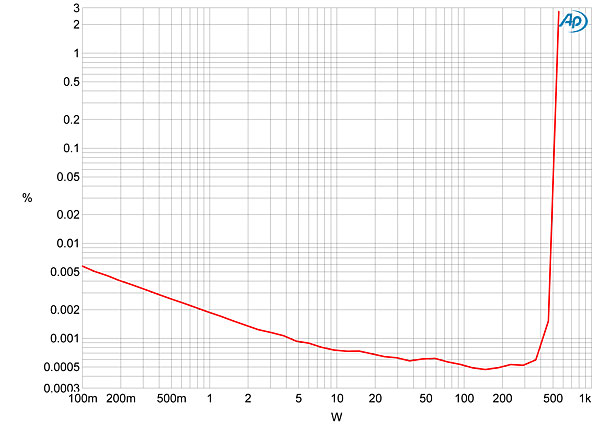
This is the effect of increasing noise with lower levels, because you measure THD+N. The only sure way to measure low level distortion is with a spectrum analysis with enough averages to get the noise down.
jan
Last edited:
Which
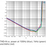
Bruno Putzeys' Class A amp, pinched the graph from Sander Sassen's home page.
(mine do close to 100/8, and way better built if i may add in my usual utterly modest self
 )
)Main point was to show the THD+N at low output level.
At 1mW output (or 1/1000th W for Mr Keiser), distortion total will undoubtedly still be way under 0.05%
Quiescent current level in the Halcro's is much higher than average, the 8.9% figure at 1mW can only be total crock.
(not saying i fancy Candy items, i'd sooner take the +100K MBL monos, despite them being just as B-ugly)
Perhaps if someone could explain how 10mA through a tube has a different number of charge carriers than 10mA though a semiconductor?
I am referring to watts, not amps here. For the same output in watts, a vacuum tube would appear to require less charge carriers than a silicon device by virtue of its much higher operating voltage.
I have posted the pics on the other page (Arcam HK, Pioneer). If that is not "go up" when you go towards low power, then I don't know what they are.
I am building amplifiers since 1982. Tried all of the variants and I know that a beefy quiescent current just reduces the cross-over distortion, doesn't eliminate it. Only class A takes care of that but... comes with other issues.
BTW, this is how a $53k monobloc class AB looks like:
Interesting......
Bruno Putzeys' Class A amp, pinched the graph from Sander Sassen's home page.
Oh, that Feedback guy again.

I bet it sounds emotionless, boring etc etc..
Need to build those babies one day. Been eye-balling them for ages... but a pair of NC400s probably makes more sense right now.
Attachments
Last edited:
Wayne do you have a link to this or is it personal communication?
Can't find it on the 'net.
jan
Yes, but I see stein has responded to this already ....
Bruno Putzeys' Class A amp, pinched the graph from Sander Sassen's home page.
(mine do close to 100/8, and way better built if i may add in my usual utterly modest self
Main point was to show the THD+N at low output level.
At 1mW output (or 1/1000th W for Mr Keiser), distortion total will undoubtedly still be way under 0.05%
Quiescent current level in the Halcro's is much higher than average, the 8.9% figure at 1mW can only be total crock.
(not saying i fancy Candy items, i'd sooner take the +100K MBL monos, despite them being just as B-ugly)
Never heard the Halcro, is it that bad or heresy ?
I am referring to watts, not amps here. For the same output in watts, a vacuum tube would appear to require less charge carriers than a silicon device by virtue of its much higher operating voltage.
Perhaps context is confusing me. The charge-carrier hypothesis is from Keith Johnson, who is generally concerned with low level stages where charge-carrier density differences would be expected to have the largest effect. The idea that this could have any relevance to output stages, which run from a hundred milliamps to a hundred amps, is... novel.
If 'charge carriers' were the issue then this effect ought to be seen in sensitive instrumentation or micro-power circuits. I don't think it is.
Much more likely, if the effect is real, is some as yet unrecognised crossover distortion mechanism in SS P-P circuits. For example (but it probably isn't this one) the non-linear input impedance of the output stage (especially if CFP) interacting with the reactive output impedance of the VAS (due to Miller compensation).
Much more likely, if the effect is real, is some as yet unrecognised crossover distortion mechanism in SS P-P circuits. For example (but it probably isn't this one) the non-linear input impedance of the output stage (especially if CFP) interacting with the reactive output impedance of the VAS (due to Miller compensation).
Just trying to understand this. Wouldn't the opposite be true, since tubes usually operate at much higher voltages than silicon, and so I would presume use less charge carriers to achieve the same power output?
I think the idea was the number of charge carriers "present" as it were, not the net number required for current flow. But this would be a good calculation to do.
One of the misconceptions IMO about supposed "granularity" in devices used in electronics is the degree to which "adjacent" regions "see" each other. This led to some whoppers in the early days of JFETs for example, when credentialed people cited the "shot noise" in the channel current. Whitlock scolded me for mentioning John Linsley-Hood's use of the term "tunneling" to further describe JFET physics in the pinchoff region, I think as much or more out of loyalty to the writer (much appreciated by me as well, but this was I believe a terminological blunder that we don't need --- things are hard enough already
).Perhaps context is confusing me. The charge-carrier hypothesis is from Keith Johnson, who is generally concerned with low level stages where charge-carrier density differences would be expected to have the largest effect. The idea that this could have any relevance to output stages, which run from a hundred milliamps to a hundred amps, is... novel.
As I cautioned I may be mis-remembering that bit (will my back issues of TAS survive the next storage space move??), although I'm fairly sure he did discuss the sheer physical macroscopy of hollow-state, primarily upon the stimulus of the interviewer. KOJ had long abandoned tubes by then and had tried to get comparable performance out of transistors. In fact he slammed Ken Stevens' CAT preamp at a show once, to Ken's dismay.
Remember as well that Keith did a good deal of the design on the Spectral power amps iirc, so is no stranger to power electronics. And well before that he worked on some very high power equipment indeed at Lawrence Livermore Labs, if I have that right (I sometimes confuse Liverwurst with Berserkley).
If 'charge carriers' were the issue then this effect ought to be seen in sensitive instrumentation or micro-power circuits. I don't think it is.
Much more likely, if the effect is real, is some as yet unrecognised crossover distortion mechanism in SS P-P circuits. For example (but it probably isn't this one) the non-linear input impedance of the output stage (especially if CFP) interacting with the reactive output impedance of the VAS (due to Miller compensation).
I agree that it's not granularity of charge carriers. Recall Hawksford's ruminations some years ago about MC preamps, which I think got ink in JAES and which several people found errrr a bit unconvincing.
Brad
Dejan,
I was very specific as to where this 12dB is applicable and no, it is not always ideal.
Allow me to explain the assumptions and context.
First, I have found these "12dB around the output stage of an over-biased [or rich bias] Class AB Push Pull" first repeatedly with tubes (triode/ultralinear).
Sometimes I put the whole 12dB into the global loop, sometimes I split it between global loops and local feedback (cathode feedback). These numbers I found by using iterative primarily listening based optimisation.
I also need to state that my objective has been to gain acceptable damping factor and a minimum for high order harmonics.
I have now looked at solid state Amplifiers and to my surprise my considerably improved Tina-Ti simulations (I have worked out how to add the correct models) show a similar minimum higher order HD for an OVERBIASED (>40mV across Re) Output stage.
In my design I have an inner loop as well as degeneration to control the gain and HD of the Voltage Amplification section so I can independently control Open Loop Gain, Inner loop gain and the amount of feedback around the output stage.
And again I find 12dB to be optimum in that it gives the lowest levels of high order rubbish while containing the low order HD.
Less feedback around the output and the picture overall gets worse, more feedback and THD falls but if we draw a curve across the tops of the HD Peaks increasing NFB appears to produce not an overall lessening of HD, but a flatter tilt of the curve, with less low order HD but more high order HD.
I will have to verify this with the real Amplifier, but for now it matches my experience with Tubes in practice, so hence I am willing to run with the number.
Ciao T
Where we differ (I think?) is in how much should be left over for global. T. mentioned that 12 dB was ideal; I don't know how he got that particular number, but I am not convinced that's always ideal.
I was very specific as to where this 12dB is applicable and no, it is not always ideal.
Allow me to explain the assumptions and context.
First, I have found these "12dB around the output stage of an over-biased [or rich bias] Class AB Push Pull" first repeatedly with tubes (triode/ultralinear).
Sometimes I put the whole 12dB into the global loop, sometimes I split it between global loops and local feedback (cathode feedback). These numbers I found by using iterative primarily listening based optimisation.
I also need to state that my objective has been to gain acceptable damping factor and a minimum for high order harmonics.
I have now looked at solid state Amplifiers and to my surprise my considerably improved Tina-Ti simulations (I have worked out how to add the correct models) show a similar minimum higher order HD for an OVERBIASED (>40mV across Re) Output stage.
In my design I have an inner loop as well as degeneration to control the gain and HD of the Voltage Amplification section so I can independently control Open Loop Gain, Inner loop gain and the amount of feedback around the output stage.
And again I find 12dB to be optimum in that it gives the lowest levels of high order rubbish while containing the low order HD.
Less feedback around the output and the picture overall gets worse, more feedback and THD falls but if we draw a curve across the tops of the HD Peaks increasing NFB appears to produce not an overall lessening of HD, but a flatter tilt of the curve, with less low order HD but more high order HD.
I will have to verify this with the real Amplifier, but for now it matches my experience with Tubes in practice, so hence I am willing to run with the number.
Ciao T
Hi,
Yet all these meters measure AVERAGE, not peak. Even on the "fast" setting you can easily have 10dB+ crestfactor for the signal.
The pretence that SPL's listening to music are low are as false as those that go on about unrealistic dynamic ranges.
I have carried SPL's meters with fast peak hold into classical concerts.
At one concert I measured 92dB AVERAGE - C-Weighted maximum at the finale of the Ravel/Mussorsky Pictures at an Exibition (row 4, centre, Royal Festival Hall London, young and very energetic russian conductor who was really giving it welly).
Who would like to suggest what the unweighted peak hold maximum SPL was?
Ciao T
All audiophiles should at least once bring an accurate sound-level pressure gauge into their listening rooms.
Yet all these meters measure AVERAGE, not peak. Even on the "fast" setting you can easily have 10dB+ crestfactor for the signal.
The pretence that SPL's listening to music are low are as false as those that go on about unrealistic dynamic ranges.
I have carried SPL's meters with fast peak hold into classical concerts.
At one concert I measured 92dB AVERAGE - C-Weighted maximum at the finale of the Ravel/Mussorsky Pictures at an Exibition (row 4, centre, Royal Festival Hall London, young and very energetic russian conductor who was really giving it welly).
Who would like to suggest what the unweighted peak hold maximum SPL was?
Ciao T
Hi,
Sure. My point is that we need to look at both ends. The point that Arthur Salvatore make is simply inaccurate. This does not mean the first watt does not matter, but that the "last watt" still matters.
I can also tell you that the lowest average SPL I measured at the concert was around 40dB, but I do not have a "negative peak hold".
Another thing we need to account for BTW is the noise of the microphones themselves, which is surprisingly high for modern small capsule recording mikes...
Ciao T
T, it was not about peaks. It was about distortion of reverberation and similar subtle details, like sounds of lips, fingers, clothes...
Sure. My point is that we need to look at both ends. The point that Arthur Salvatore make is simply inaccurate. This does not mean the first watt does not matter, but that the "last watt" still matters.
I can also tell you that the lowest average SPL I measured at the concert was around 40dB, but I do not have a "negative peak hold".
Another thing we need to account for BTW is the noise of the microphones themselves, which is surprisingly high for modern small capsule recording mikes...
Ciao T
Hi,
Here is a good one.
When I look at music on a scope other screen representation it is shown as wriggly line. How can we tell that this line actually represents different sounds? What technical analyser can we use to tell me which part of the line is the first violin and which is the third Viola?
An AP2 cannot.
Ciao T
One more point is, are noises heard separate, or as if sounds are mixed with them like butter mixed with pourage.
Here is a good one.
When I look at music on a scope other screen representation it is shown as wriggly line. How can we tell that this line actually represents different sounds? What technical analyser can we use to tell me which part of the line is the first violin and which is the third Viola?
An AP2 cannot.
Ciao T
- Status
- Not open for further replies.
- Home
- Member Areas
- The Lounge
- Sound Quality Vs. Measurements