Brad, doesn't this ring of two have poor neg supply PSRR?
jan
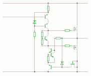
And as one contemplates it, the ring of two is a lot better for PSR than it might appear at first. The sensitivity of the effective reference voltage, Vbe of the error amp transistor Q1, to changes in the power supply via R1, is reciprocal to the transconductance of that device. And the input impedance at the base of Q2 is low, again due to feedback. So if we wiggle the power supply voltage, the major effect is reference voltage modulation, and that is about (delta V)/(R1*gm), and the effect on output current is calculated as the ratio of that to the emitter resistor R3.
If R1 is replaced by a higher-impedance source of current things get a lot better still. But for two transistors the performance is pretty nice.
Hi,
Okay. Monkeywrench:
Ciao T
Eh? Come again?
T., I think a small diagram would make things comprehensible again.
Okay. Monkeywrench:
An externally hosted image should be here but it was not working when we last tested it.
Ciao T
Attachments
Hi,
Okay. Monkeywrench:
Ciao T
I guess I like everything about that except the propensity to bottom out for sagging negative rail voltages, which I gather in the case of the Hafler is a real concern. With good rail regulation it should work great.
Hi,
Okay. Monkeywrench:
An externally hosted image should be here but it was not working when we last tested it.
Ciao T
Duh ... d red ting up dere, anoder immortal Loesch family invention?

I get it now, thank you Thorsten. You already know I'm a bit thick. I get it in the first pass at the same rate wisdom teeth come out.
Bootstrapped current source. Like oiled butter.
Perhaps with you, my Polish cousin. But with Thorsten, things are always nuclear.

I guess I like everything about that except the propensity to bottom out for sagging negative rail voltages, which I gather in the case of the Hafler is a real concern. With good rail regulation it should work great.
Yes and no. Yes the 54 volt rails collapse like any mutual fund I ever bought, but for the moderate level loads this amp is intended for, it can probably hold up to rated output needing about 36 or so volts. I also have twice the main bank as original. I'll model the above suggestions. A volt or two would be worth it if it could pass the hearing test. All learning, circuits and sim. I could always call it a DH-60, increase feedback a bit, and claim 3dB overhead! Or in the way of modern advertising, 120W of dynamic music power.
There is a lot to take in in the last few posts. I am working on being able to visualize the current flow. I can get about half way there. Maybe if I draw a picture with more of the secondary features, like all the caps. This may sound strange, but I am very good at visualizing things that others can't. Stress in a structure, waves, what things will look like. I should be able to internalize a two transistor circuit fully. Trying to picture Early and temperature at the same time is hard on my beer budget of one per day. I guess in the 60's at some well known West coast universities, other , shall I say methods?, were taken advantage of. With all due respect to Timothy. I remember them because I was too young not too.
And to think, I never replaced my Beta version of A Clockwork Orange. Now there is an altered state for you. Not as far out as some of the cartoons that came out of Eastern Block countries "in the day". I remember "The Man Who Had To Sing" .This was about the time of the immortal short, Bambi vs. Godzilla. It was a good time to be a cartoon fan. No modern CGI can match what a Tex Avery could do.
Not as far out as some of the cartoons that came out of Eastern Block countries "in the day". I remember "The Man Who Had To Sing" .This was about the time of the immortal short, Bambi vs. Godzilla. It was a good time to be a cartoon fan. No modern CGI can match what a Tex Avery could do.
How about Jan Lenica, or Trinka's "The Hand". On this subject I could go on forever, Zagreb studios had many great shorts.
Hi,
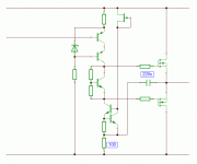
Well, if it drops out, it drops out. The ring of two drops out < 1V, the emitter follower maybe another 0.7V. Should not be really THAT much worse than original.
But yes, a separate boosted set of supply rails for the frontend would help.
BTW, there is of course the other option, a 100 Ohm resistor in series to the ring of two CCS and a 220uF electolytic capacitor from the junction to the output, but that option is entierly too obvious and way to simple for the "if uses ten parts where one will do it has to be good" brigade... Plus the active version should be a trifle better.
Ciao T
I guess I like everything about that except the propensity to bottom out for sagging negative rail voltages, which I gather in the case of the Hafler is a real concern. With good rail regulation it should work great.
Well, if it drops out, it drops out. The ring of two drops out < 1V, the emitter follower maybe another 0.7V. Should not be really THAT much worse than original.
But yes, a separate boosted set of supply rails for the frontend would help.
BTW, there is of course the other option, a 100 Ohm resistor in series to the ring of two CCS and a 220uF electolytic capacitor from the junction to the output, but that option is entierly too obvious and way to simple for the "if uses ten parts where one will do it has to be good" brigade... Plus the active version should be a trifle better.
Ciao T
Attachments
Last edited:
And as one contemplates it, the ring of two is a lot better for PSR than it might appear at first. The sensitivity of the effective reference voltage, Vbe of the error amp transistor Q1, to changes in the power supply via R1, is reciprocal to the transconductance of that device. And the input impedance at the base of Q2 is low, again due to feedback. So if we wiggle the power supply voltage, the major effect is reference voltage modulation, and that is about (delta V)/(R1*gm), and the effect on output current is calculated as the ratio of that to the emitter resistor R3.
If R1 is replaced by a higher-impedance source of current things get a lot better still. But for two transistors the performance is pretty nice.
OK. Yes replacing R1 with a simple CCS would also be my preference.
jan
By the way, the quality of the second stage current source is fairly immaterial.
Adding a "beta-enhancing" emitter follower between the first stage and the second helps, but splitting the compensation up (two C in series, each with twice the value of the original Miller C, with a 1k or thereabouts from overall output to the junction of the C's, as discussed in Self's Linear Audio Vol. 0 article) has a huge effect.
Adding a "beta-enhancing" emitter follower between the first stage and the second helps, but splitting the compensation up (two C in series, each with twice the value of the original Miller C, with a 1k or thereabouts from overall output to the junction of the C's, as discussed in Self's Linear Audio Vol. 0 article) has a huge effect.
Last edited:
My daughter speaks German pretty well, she learns it in school. Tomorrow we are meeting an exchange student from Germany. 2 years after will be her turn to go to Germany...
Wonderful opportunity.
What I am finding in Spice pretty quick I am at the limit of the simulation. I can make things worse, but not much better. Changing the bias for the VAS cascode to tap below the restored 27 Ohm degeneration did give a couple dB improvement. About to the limit.
I don't understand it. Just a voltage source and a 1K resistor is about what I am measuring on the amp. Moving over to bother the spice forum for a bit to see what the problem is with the spice sine source.
I don't understand it. Just a voltage source and a 1K resistor is about what I am measuring on the amp. Moving over to bother the spice forum for a bit to see what the problem is with the spice sine source.
Think I got the FFT figured out. It was not in extended precision mode. This caused about 30 dB of noise masking everything I have been trying to do.
Now to go back and re-do a weeks worth of tests.
You made some remarks a while back about the clamp zeners, their apparent contribution to distortion, and whether they were necessary or not. Attached is a way of using two zeners with biasing and small-signal diodes with much lower capacitance to mitigate any effects of variable C. There is a small amount of current pulled from the rails to keep the zeners biased on, and a tiny bit of additional loading on the output with signal swing.
So two zeners are saved, and four small-signal diodes are added (~1N4148 would work fine for ~50V rails).
It's possible that in some circumstances the traces to the FETs might be a little long, i.e., high inductance, in which case local zeners for each transistor might be indicated.
Attachments
Well, that's it. I think this its final form, although values will change as testing progresses.
In the end, I decided not to use FETs. Several reasons for this. Local suppliers are VERY erratic about stocking them, and I don't want to use parts which I am not sure I can buy again, the alternative being to stockpile them, and frankly, I am sick and tired of stockpiling things
On the sonic front, I am still not convinced that they are sure to bring improvement. I am not saying they don't, but I don't see them as a prerequisite for good sound. Some of the best amps I have ever heard didn't have them anywhere in sight.
On the other hand, if I give the lower pair a somewhat higher voltage, like 20V as I did on the schematic, this would allow me to have all four transistor for each half of the sine wave as low noise BC 550/560 B. And them I already have stockpiled, original Siemens parts, 140+150 pcs, some already selected as matching pairs. Also, if I should happen to find the now discontinued Analog Devices MAT units, I think I'll be still better off.
The biggest difference are the CCS. They are now relatively complex circuits, even very complex for what we sometimes see in that position elsewhere, but I think these will prove to be above average.
Lastly, I have reduced the overall gain and overall NFB, down from around 30 dB to my more usual value of 26 dB (strictly speaking, 25.77 dB). While I own units with less to much less overall NFB, I believe a little more global feedback is better yet for the sound. Extremely low, and especially zero global NFB amps sound somehow a little loose, to me, a little rounded off, as if they were not quite finished. For example, my H/K 6550 (17 dB NFB) sounds better defined to me than the more powerful H/K 680 (12 dB NFB).
Of course, I could be wrong on that point, but at this time, that's how I see it.
Initial measurements show an open loop full power bandwidth out to 55 kHz. With NFB, it extends to over 300 kHz, but I have half a mind to do what Revox and Sony did - let it go as far as you can, then install a first order low pass filter at say 200 kHz - cover your bases, so to speak.
Full power 1 kHz THD open loop is 0.342% into 4 Ohms, which is reasonable. Closed loop 20-20,000 Hz THD is 0.44% into 4 Ohms and 0.028% into 8 Ohms, both also at full nominal power. Wahab will probably not be happy, but I can't please everyone. Also, I feel there's much more to good sound than plain THD and IM measurements.
The protection has been fixed so that it allows for full votage swing even into 2 Ohms, but will act if the impedance reaches 1.8 Ohms.
What I love about it is that all forms of distortion almost linearily decrease with reduced power, but there's no distortion comeback - at 0.5W/8 Ohms, it drops to 0,005%. The bias current for the output transistors has been set at 120 mA per transistor.
Attachments
Last edited:
Hi,
Then consider buffering the inputs.
I would probably suggest to instead keep simple ones and bootstrap the CCS AND the cascodes to the common mode signal. It can be done using a minimal number of extra parts and they are all resistors.
The CCS's should do much better (as you effectively keep the voltage conditions under which they work constant) and the cascodes now rigidly lock the voltages across the amplification transistors without common mode related swings.
Ciao T
In the end, I decided not to use FETs.
Then consider buffering the inputs.
The biggest difference are the CCS. They are now relatively complex circuits, even very complex for what we sometimes see in that position elsewhere, but I think these will prove to be above average.
I would probably suggest to instead keep simple ones and bootstrap the CCS AND the cascodes to the common mode signal. It can be done using a minimal number of extra parts and they are all resistors.
The CCS's should do much better (as you effectively keep the voltage conditions under which they work constant) and the cascodes now rigidly lock the voltages across the amplification transistors without common mode related swings.
Ciao T
- Status
- Not open for further replies.
- Home
- Member Areas
- The Lounge
- Sound Quality Vs. Measurements