Hi,
Well, that depends on your definition of "better".
Better sonics...!
My Amp will already have 4pcs 18,000uF per channel (72,000uF per channel in magazine Spec's) so how much bigger can we realistically get?
Well that's OK if for 200 watt max amplifier, some may like the sound of their lower filtered supplies ..
")
Chokes store energy, resistors do not.
Chokes give a 2nd order filter, resistors a 1st.
The so-called "really big cap's" have their own problems.
OK, what exactly, what are the negativities of going with big psu (250,000uf/ch for eg.) storage, of course with bypass caps and smaller caps right at outputs.
As I am not trying to drive speakers with 75dB/2.83V/1m efficiency and sub 1 ohm bass impedance I do not see the need for stupidly big PSU Cap's.
Hey now...
It's ....79db.....As a rule, bigger values are better, but for me (existing chassis/PCB's that must accept modification) size was the main constraint, so I asked the factory that made the samples to give me something for 10A DC, 50mOhm DCR per choke and the given size core and the maximum "L" that would go for this. They came out at 1mH appx...
Ciao T
Bigger as in say a 10 mh choke, laminate or aircore odds are the impedance will be low , if not using specific transformer as you ...
3685 followup --- comparison of two very similar sources
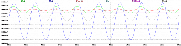
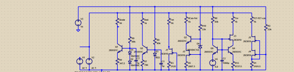
So what we see here are two bipolar/JFET ~5mA I sources (or sinks). Both have an output resistance of 394Mohm. The output capacitance out to about 1-2 MHz of the one with gate to emitter feedback is about 58fF, of the other 1.7pF out to >100MHz.
When we contrive to examine the distortion associated potentially with the voltage-variable output capacitance of each, loaded with a "perfect" current source and a 1Mohm resistor, and drive with a +/- 1uA current signal, thus getting a +/-1V signal at the drains, we see THD out to the tenth harmonic of 2544ppm for the left hand one, 44.6ppm for the right. Second harmonic dominates for both, at -52.5dBr and -86.9dBr respectively. Third is -81dBr for the left circuit and -121dBr for the right. Of course these are sweet Spice lies, but maybe not too ridiculously so.
In many practical applications this performance may be irrelevant --- what can we load such a circuit with that doesn't itself contribute a boatload more of variable C etc.? Well, good question
BTW the "2SC1815A1" is roughly comparable to a 2SC1815BL (the highest-beta sort).
Attachments
Last edited:
Hi,
...
Second is that I'm a tube guy and if I see two identical capacitors on the same rail I feel someone has forgotten the filter choke that goes inbetween.
...
Unless you do it right from the start - filter out the mains hash BEFORE it even reaches your device. And not just the power amp, but your entire system.
Wihtout any false modesty, my power line filters have got by far the greatest raves from tube audio owners, and among them, in particular Research Audio gear owners.
I don't want to plug them, I'm merely saying that filtering after the power transformers is acting after the fact, so to speak - I hope there is no-one here who believes that powwer transformers are not stressed by line hash. When they start humming is only the last stage, by that time, you have a catastrophe on your hands.
You can actually measure this as simple off load power consumption without or with - with is 7...10% less. And your power supplies have to deal with this c**p whether you like it or not.
With all respect, T., filtering is far more efficient and thorough BEFORE all that junk even gets to the transformer and starts to stress it. You discover that with efficient external filtering bofre the device your transformers become noticeably more efficient, so for the same effect, feel free to use one size down (say, a 400 VA unit instead of a 500 VA unit) as you lose nothing.
Lastly, a quality filter battery will filter the power of the entire system, in addition from preventing anything happening among devices attached, as would happen with a single filter; it would protect from the grid, but not from each other AFTER the filter. My way, where each output has its own filter, is about as good as it gets, albeit for a price - this is ESPECIALLY true of tube audio, as demonstrated over the last 11 years.
Just giving you thought food.
Hi,
In my particular schematic above, if you vary the temperature, nothing much happens, hence the LM329 (essentially zero tempco) AND the BC550... A monolithic dual would be better, for most uses the thermally coupled individual ones work well...
Ciao T
Ok, it is good that you got high dynamic resistance, and it is good that it is equally high on wide frequency band!
Now, what happens when you vary temperature?
In my particular schematic above, if you vary the temperature, nothing much happens, hence the LM329 (essentially zero tempco) AND the BC550... A monolithic dual would be better, for most uses the thermally coupled individual ones work well...
Ciao T
Dejan,
There are many ways here. Filters are limited. I generally my stuff so it does not need them.
The chokes in the PSU are used to kill rectifier noise/ripple. Your filters cannot do that.
I am not surprised. I really do not want to say more...
No food there. I have from day one considered the "needs external filter" approach flawed, maybe a result of exposure to german pro-gear, which has it all build in.
Ciao T
Unless you do it right from the start - filter out the mains hash BEFORE it even reaches your device. And not just the power amp, but your entire system.
There are many ways here. Filters are limited. I generally my stuff so it does not need them.
The chokes in the PSU are used to kill rectifier noise/ripple. Your filters cannot do that.
Wihtout any false modesty, my power line filters have got by far the greatest raves from tube audio owners, and among them, in particular Research Audio gear owners.
I am not surprised. I really do not want to say more...
Just giving you thought food.
No food there. I have from day one considered the "needs external filter" approach flawed, maybe a result of exposure to german pro-gear, which has it all build in.
Ciao T
Dejan,
There are many ways here. Filters are limited. I generally my stuff so it does not need them.
...
The chokes in the PSU are used to kill rectifier noise/ripple. Your filters cannot do that.
...
I am not surprised. I really do not want to say more...
...
No food there. I have from day one considered the "needs external filter" approach flawed, maybe a result of exposure to german pro-gear, which has it all build in.
Ciao T
If you ever want to give it a try, just let me know, we'll work something out. Ultimately, I'll send you DIY kit.

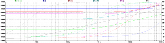
If I am reading the following correctly, the single FET CCS is the best linearity, but not great impedance. The cascode fet-fet has by far the best LF performance.
So with this set of options, one must choose for low frequency performance or linearity. Better transistors may change everything, as will when I put them in the complete model. Of course, then there is reality.
So with this set of options, one must choose for low frequency performance or linearity. Better transistors may change everything, as will when I put them in the complete model. Of course, then there is reality.
Attachments
If I am reading the following correctly, the single FET CCS is the best linearity, but not great impedance. The cascode fet-fet has by far the best LF performance.
So with this set of options, one must choose for low frequency performance or linearity. Better transistors may change everything, as will when I put them in the complete model. Of course, then there is reality.
If the impedance is high enough, who cares how it varies with voltage?
Variation IS a potential distortion mechanism, important to different degrees depending upon the circuit in which the variable thing is embedded. The distortion will be different if the variation is linear as opposed to nonlinear. But it will still be distortion.
And yes, the bipolar-JFET combo will work best, especially if the gate is returned to the emitter (see my posted comparison circuits above), AND if you have enough voltage in the circuit to pinch off the JFET. Which, for your application as a tail current generator in an amplifier with substantial closed-loop gain, you do.
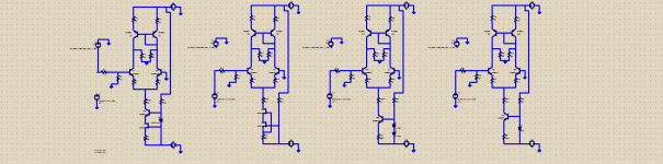
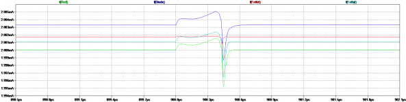
Made up a copy of the 120 IPS. Grounded the negative input. Just 50K loads. It was more revealing about steps in load. Set to 2 mA tail current. Again the twin FET outperformed the other configurations. Looking at the FFT, there were no appreciable differences looking at the first stage output.
I admit to pretty much guessing at a lot of the part values, considering I was guessing with what was in Spice.
I admit to pretty much guessing at a lot of the part values, considering I was guessing with what was in Spice.
Attachments
Unless you do it right from the start - filter out the mains hash BEFORE it even reaches your device. And not just the power amp, but your entire system.
Wihtout any false modesty, my power line filters have got by far the greatest raves from tube audio owners, and among them, in particular Research Audio gear owners.
I don't want to plug them, I'm merely saying that filtering after the power transformers is acting after the fact, so to speak - I hope there is no-one here who believes that powwer transformers are not stressed by line hash. When they start humming is only the last stage, by that time, you have a catastrophe on your hands.
You can actually measure this as simple off load power consumption without or with - with is 7...10% less. And your power supplies have to deal with this c**p whether you like it or not.
With all respect, T., filtering is far more efficient and thorough BEFORE all that junk even gets to the transformer and starts to stress it. You discover that with efficient external filtering bofre the device your transformers become noticeably more efficient, so for the same effect, feel free to use one size down (say, a 400 VA unit instead of a 500 VA unit) as you lose nothing.
Lastly, a quality filter battery will filter the power of the entire system, in addition from preventing anything happening among devices attached, as would happen with a single filter; it would protect from the grid, but not from each other AFTER the filter. My way, where each output has its own filter, is about as good as it gets, albeit for a price - this is ESPECIALLY true of tube audio, as demonstrated over the last 11 years.
Just giving you thought food.
Batteries ....! Dead sound ..........
Hi,
Well, that depends on your definition of "better".
My Amp will already have 4pcs 18,000uF per channel (72,000uF per channel in magazine Spec's) so how much bigger can we realistically get?
Chokes store energy, resistors do not.
Chokes give a 2nd order filter, resistors a 1st.
The so-called "really big cap's" have their own problems.
As I am not trying to drive speakers with 75dB/2.83V/1m efficiency and sub 1 ohm bass impedance I do not see the need for stupidly big PSU Cap's.
As a rule, bigger values are better, but for me (existing chassis/PCB's that must accept modification) size was the main constraint, so I asked the factory that made the samples to give me something for 10A DC, 50mOhm DCR per choke and the given size core and the maximum "L" that would go for this. They came out at 1mH appx...
Ciao T
Back in the 70's I put one FARED on each rail of a sub amp. Had to sequence it up with light bulbs. Made noise for about two days after it was powered off. If nothing, it proved it was totally useless for anything other than bragging rights. We had surplus dealers back then, and surplus big Mallory 100,000uf caps that were most likely full pf PCB's.
Full amp testing. To do this, I removed the old bias string.
Stock, original bias string, average -70dB
Diode IPS, CM VAS -81 dB
fet/bjt both IPS and VAS -70 dB ( third harmonic was worse)
Cascode fet/bjt IPC, CS VAS -81 dB
fet/fet cascode both IPS and VAS -85 dB
The majority of the improvement is in the VAS. Not surprised as a lot of amps I have seen keep the "cheap" diode CCS in the IPS and use a CM in the VAS.
So the predicted distortion ( average of 3rd through 6th) relates quite well to the impedance and step transients in the isolated model. The simple answer is cascoded fets. I know nothing about noise or thermal tracking. 1.3mA in IPS, 3.4 mA in VAS.
Well, dinner time and I have to get back to my real job in the morning. Very informative weekend. Thanks for the assistance.
Last edited:
I hope there is no-one here who believes that powwer transformers are not stressed by line hash. When they start humming is only the last stage, by that time, you have a catastrophe on your hands.
You can actually measure this as simple off load power consumption without or with - with is 7...10% less. And your power supplies have to deal with this c**p whether you like it or not.
I'm curious - what is the hash here? Stuff in the 10kHz - 100kHz band from SMPSUs? If such high frequency then how might it stress the transformer? Doesn't the transformer look like a big lossy inductor to the mains supply? Is your meaning of 'stress' increasing the flux in the core much closer to, or even into, saturation?
@dvv
" I hope there is no-one here who believes that powwer transformers are not stressed by line hash. When they start humming is only the last stage, by that time, you have a catastrophe on your hands."
What on earth is that all about??
You must be drinking something very different to me
edit: didn't see Abraxalito's comment
So what we see here are two bipolar/JFET ~5mA I sources (or sinks). Both have an output resistance of 394Mohm. The output capacitance out to about 1-2 MHz of the one with gate to emitter feedback is about 58fF, of the other 1.7pF out to >100MHz.
When we contrive to examine the distortion associated potentially with the voltage-variable output capacitance of each, loaded with a "perfect" current source and a 1Mohm resistor, and drive with a +/- 1uA current signal, thus getting a +/-1V signal at the drains, we see THD out to the tenth harmonic of 2544ppm for the left hand one, 44.6ppm for the right. Second harmonic dominates for both, at -52.5dBr and -86.9dBr respectively. Third is -81dBr for the left circuit and -121dBr for the right. Of course these are sweet Spice lies, but maybe not too ridiculously so.
In many practical applications this performance may be irrelevant --- what can we load such a circuit with that doesn't itself contribute a boatload more of variable C etc.? Well, good question
BTW the "2SC1815A1" is roughly comparable to a 2SC1815BL (the highest-beta sort).
Working on my visualization. I see how the right hand circuit works, but not quite there on the left. Of course the sim has perfect bias.
Working on my visualization. I see how the right hand circuit works, but not quite there on the left. Of course the sim has perfect bias.
The left-hand side is a conventional bipolar-JFET cascode. Any currents that flow into the JFET gate are "grounded out" through the (ideal) voltage reference. The output impedance at the JFET drain is a very high resistance as stated, in parallel with the drain-gate capacitance. Very useful, and for the purpose of a diff pair tail current generator, certainly quite adequate in most any situation. Probably indistinguishable from a "perfect" current source.
On the right, those gate currents due to a.c. on the drain and the aforementioned Cdg (plus the tiny leakage current), divide up between the bipolar's emitter and the 1k emitter resistor, weighted by the respective conductances. The admittance at the emitter is very high relative to 1/1k (something in the vicinity of 160 millisiemens, the reciprocal of ~6 ohms). So the lion's share by far of the gate current goes into the emitter, and thus is not lost --- it's pumped back out the collector, with a loss of only the base current. This effects a gigantic reduction in output capacitance over a very useful frequency range. Again, for a power amp's input stage, it's pretty much "Who cares??" In other circuits it can be significant and very helpful.
Brad
I think something was lost in translation... At least I hopeI'm curious - what is the hash here?
Hi,
I find that in this case QUALITY trumps QUANTITY, unless you are a "bass-pig" who only cares about stunt bass, midrange and treble be damned.
For the Elna "For Audio" you need around 10 times the value in generic cap's to get the distortion equally low (Self in WW).
Somewhere I posted about a test (listening, blind) we did concerning PSU Cap's in poweramp's. The "wrong" brand cap's (one often seen in Audio Gear because it is considered "high quality") sounded rather bad, despite having a full regulation circuit (Gyrator with tripple darlington) between the reservoir cap's and the supplied Amp.
My Amp will use 56V rails and hence will probably qualify as 150WPC, maybe 180WPC.
As for "lower filtered supply", you need an impractical 500,000uF per rail to get the same Peak-Peak ripple as my 18,000uF -> 2mH -> 18,000uF supply, HOWEVER the 500,000uF Supply still outputs a buzzy sawtooth with ton's of higher harmonics, while "lower filtered supply" actually leaves a mostly clean sinewave.
So I guess you are right, some may like the sound of their LOW FILTERED supplies, that is ones that just big capacitance after the rectifier instead of LC Filters.
Incidentally, I personally tend towards regulated supplies over LC for high power applications, however in this particular case this was not really an option, as the chokes have space on the PCB and can fit the PCB with 2 minutes work, while complete PSU redesign would mean a lot of work...
The bigger cap's will minimise the conduction angle in the supply. The bigger the first cap in a given supply, the higher the peak currents drawn and the narrower the charge pulses.
This has wide reaching consequences, from more high order components in the Supply output to issues with radiated rectification noise and to increased problems from rectifier switchoff.
So it is like a mini version of the problems caused by SMPS's...
Sure, all these problems are subtle and their consequences are subtle, but clearly measurable and audible, especially in Tube Amp's, where I spend most my time. As this Amplifier as intended has many parallels with Tube Amplifiers Tube Amp style supplies will not do harm.
As said, bigger is better, but you must avoid excessive DCR. Chokes are not created equal either, just like capacitors.
Also, consider using the minimum capacitance that works (ripple current rating with reserve) before the choke and the big capacitors after...
Ciao T
Better sonics...!
I find that in this case QUALITY trumps QUANTITY, unless you are a "bass-pig" who only cares about stunt bass, midrange and treble be damned.
For the Elna "For Audio" you need around 10 times the value in generic cap's to get the distortion equally low (Self in WW).
Somewhere I posted about a test (listening, blind) we did concerning PSU Cap's in poweramp's. The "wrong" brand cap's (one often seen in Audio Gear because it is considered "high quality") sounded rather bad, despite having a full regulation circuit (Gyrator with tripple darlington) between the reservoir cap's and the supplied Amp.
Well that's OK if for 200 watt max amplifier, some may like the sound of their lower filtered supplies ..
My Amp will use 56V rails and hence will probably qualify as 150WPC, maybe 180WPC.
As for "lower filtered supply", you need an impractical 500,000uF per rail to get the same Peak-Peak ripple as my 18,000uF -> 2mH -> 18,000uF supply, HOWEVER the 500,000uF Supply still outputs a buzzy sawtooth with ton's of higher harmonics, while "lower filtered supply" actually leaves a mostly clean sinewave.
So I guess you are right, some may like the sound of their LOW FILTERED supplies, that is ones that just big capacitance after the rectifier instead of LC Filters.
Incidentally, I personally tend towards regulated supplies over LC for high power applications, however in this particular case this was not really an option, as the chokes have space on the PCB and can fit the PCB with 2 minutes work, while complete PSU redesign would mean a lot of work...
OK, what exactly, what are the negativities of going with big psu (250,000uf/ch for eg.) storage, of course with bypass caps and smaller caps right at outputs.
The bigger cap's will minimise the conduction angle in the supply. The bigger the first cap in a given supply, the higher the peak currents drawn and the narrower the charge pulses.
This has wide reaching consequences, from more high order components in the Supply output to issues with radiated rectification noise and to increased problems from rectifier switchoff.
So it is like a mini version of the problems caused by SMPS's...
Sure, all these problems are subtle and their consequences are subtle, but clearly measurable and audible, especially in Tube Amp's, where I spend most my time. As this Amplifier as intended has many parallels with Tube Amplifiers Tube Amp style supplies will not do harm.
Bigger as in say a 10 mh choke, laminate or aircore odds are the impedance will be low , if not using specific transformer as you ...
As said, bigger is better, but you must avoid excessive DCR. Chokes are not created equal either, just like capacitors.
Also, consider using the minimum capacitance that works (ripple current rating with reserve) before the choke and the big capacitors after...
Ciao T
- Status
- Not open for further replies.
- Home
- Member Areas
- The Lounge
- Sound Quality Vs. Measurements