There is no limit where one could go with FET inputs, doubling the outputs, newer transistors, metal film resistors, splitting the power rails with a cap multiplier or pi filter, DC servo, whatever. It's a 35 year old amp with no protection, power control, mute, or modern niceties.
Funny coincidence, I found 3 220's in my storage area and was thinking of halving the PS voltage and upping the bias to an amp or so and replacing the input with something between a JC-3 and F5. A single folded cascode input for voltage gain and the existing output for current gain. Then I found that this ground has been covered before. Luckily my wife could care less how it sounds.
So here is the final config for the DH-120.
Have a look at this and give consideration to where the diode strings of your cascode reference terminate:
http://www.essex.ac.uk/csee/research/audio_lab/malcolmspubdocs/J10%20Enhanced%20cascode.pdf
<edit> Also Samuel Groner has things to say about current mirrors:
http://www.sg-acoustics.ch/analogue_audio/power_amplifiers/index.html
Last edited:
I have one more 220 on the shelf too. I think it will hit e-bay soon.
I don't understand why you would up the bias. From what I understand, the L-FETS like a bit less, 110mA per or so. The 220 does have the full complementary input. But it is still a pain packaging.
Instead of reducing the PS, how about just regulating the VAS and IPS at a lower voltage? Say 40V?
I don't understand why you would up the bias. From what I understand, the L-FETS like a bit less, 110mA per or so. The 220 does have the full complementary input. But it is still a pain packaging.
Instead of reducing the PS, how about just regulating the VAS and IPS at a lower voltage? Say 40V?
Have a look at this and give consideration to where the diode strings of your cascode reference terminate:
http://www.essex.ac.uk/csee/research/audio_lab/malcolmspubdocs/J10%20Enhanced%20cascode.pdf
<edit> Also Samuel Groner has things to say about current mirrors:
SG-Acoustics · Samuel Groner · Power Amplifiers
Cool. This will give me some study time. I am also trying to get through Mr. Pass's papers. To really go further I need to build a test amp that is easier to work on. I have an old Yamaha AVR that I am going to gut into a test bed that is easier to work on and change stuff. For basic amp, I have a pair of "MX-50" cards that cost all of twelve bucks that are a very conventional design. I won't be paranoid of blowing 60 bucks of outputs.
Chomsky was greatly raised in my esteem by taking on Skinner. BTW my wife and I went to an open house next door to the Skinner residence many years ago, there goes the neighborhood.
Although I have to search very deeply in my stores of compassion to feel a bit sorry for him, it was rather hilarious to have both Chomsky and Ayn Rand write scathing reviews of Skinner's Verbal Behavior. Skinner claimed he never read them.
Later on, once again, both wrote reviews of Beyond Freedom and Dignity. I haven't seen the Chomsky one, but I have a copy of the Ayn Rand Letter with her account of the book, and this time with a mention of Chomsky, which although she points out is "someone from the New Left" (or words to that effect), quotes him and does so approvingly!
Remembering my friend Steven Epstein, the Skinner devotee (and budding neurophysiologist --- he lamented that he couldn't get away with killing his very nice and down-to-earth brother Mike, who was taking up space in the family home that Steven would have put to "better" use for lab space), I purchased a copy of Verbal Behavior from an online seller. I had it for a few years and finally noticed a low-key inscription on the FFEP. The book had belonged to one Sylvia Thorpe, but it was apparently given to her by a "Fred".
I conjectured that this might indeed be Burrhus Frederic Skinner, which another friend guffawed at. At a book fair I asked a person selling autographs (and having a very bad day) how I might go about authenticating this. He said Oh there's probably some %^&^$ Skinner Society or some bloody thing.
There indeed was. I wrote to Julie Vargas, the president. She asked to see a photocopy of the FFEP, and sent me a letter. "Yes, that is definitely my father's signature". Her full name being Julie Skinner Vargas.
I mentioned this to a bookseller friend with whom I'd shared the notion. He said, Yes, he signed things "Fred". He had withheld this information until I told him of the authentication.
Why not build an F5 turbo ......")
Tons of choices. B3? That is an entire different direction. Might be fun.
Hi,
Good work. I understand you don't want to do any more work, seeing as it is a PITA to work on the Amp. Please let us know the reactions of your wife to the Amp...
Ciao T
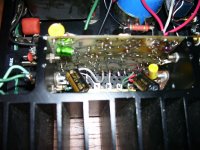
After a week of struggling, it is now rock solid, BW of over 80K, symmetrical. So here is the final config for the DH-120.
View attachment 271011
Good work. I understand you don't want to do any more work, seeing as it is a PITA to work on the Amp. Please let us know the reactions of your wife to the Amp...
Ciao T
Have a look at this and give consideration to where the diode strings of your cascode reference terminate:
http://www.essex.ac.uk/csee/research/audio_lab/malcolmspubdocs/J10%20Enhanced%20cascode.pdf
<edit> Also Samuel Groner has things to say about current mirrors:
SG-Acoustics · Samuel Groner · Power Amplifiers
I can't help commenting ...
M. Hawksford is, in my book, an old and trusted address which has been there for a long, long time. Every time I took his word, I was better off afterwards.
I haven't read (just flipped through to discover it's worth the read) S. Groner's text, but I did catch a few interesting details even on the fly (I will read it all later on).
It constantly amazes me how some things I hold to be common knowledge have to wait for decades for the scientists to show how and why it is better than many of the rest.
Case in point - BC 550/560 trannies. They are usually used because of their nominal very low noise figure, this being the most common reason given for their existence in a circuit. However, there's a graph comparing them with Motorola's 8099 trannies, which shows that initially, the BC trannies do have a higher level of distortion than the 8099, but higher up in the range, their distortion rises much less than the 8099.
This corresponds exactly to my experience. You may have noticed that I have a sweet spot for Motorola in general, and their power devices in particular - this is true. But over the years, for reasons I can explain only as a feeling that the BC trannies "sound better overall", I have ditched the 80xx family in favor of the BC family.
That would mean little, if anything, if it was just me, but the entire circle of my friends who are into electronics did exactly the same, for more or less the same reasons - they simply sound more natural to what appers to be quite a few people.
My cascode would use BC 550/560 as the actual input pair and BC 546/556 as the "upper" pair. I was told, many years ago, by an engneer from Siemens who was in transistor manufacturing, that BC 550/560, 546/556 and 547/557 were in fact made in the same general batch, and were selected for propreties and arranged in families by sample selection later on. At the time, early 80ies, this shocked me, I suppose I expected to hear of some exotic process they used.
I had no other option available to me but a concerete, sample-by-sample try. To my surprise, I discovered that well over one half of the randomly chosen BC 550/560 population, although rated at 45V, lived on to 55V or a bit above without any particular problems. Ditto for 547/557, also rated for 45V, also do mostly fine by 55V. BTW, all were made by Siemens, I try very hard to make sure my BC family trannies all come from Siemens, having found them to be extremely reliable.
Now I am about to read appearently why my purely subjective evaluation was in fact based on hard science without my knowing it.
Hi,
You really need to read the whole article and look carefully under which conditions this applies and what the surrounding circumstances are.
Then you realise that there are no "blanket" statements about transistor linearity possible.
Generally bipolar transistors when driven by high source impedances (which is the case in this circuit) are current driven, not voltage, which has a number of interesting consequences.
Ciao T
Case in point - BC 550/560 trannies. They are usually used because of their nominal very low noise figure, this being the most common reason given for their existence in a circuit. However, there's a graph comparing them with Motorola's 8099 trannies, which shows that initially, the BC trannies do have a higher level of distortion than the 8099, but higher up in the range, their distortion rises much less than the 8099.
You really need to read the whole article and look carefully under which conditions this applies and what the surrounding circumstances are.
Then you realise that there are no "blanket" statements about transistor linearity possible.
Generally bipolar transistors when driven by high source impedances (which is the case in this circuit) are current driven, not voltage, which has a number of interesting consequences.
Ciao T
Hi,
You really need to read the whole article and look carefully under which conditions this applies and what the surrounding circumstances are.
Then you realise that there are no "blanket" statements about transistor linearity possible.
Generally bipolar transistors when driven by high source impedances (which is the case in this circuit) are current driven, not voltage, which has a number of interesting consequences.
Ciao T
That's true, but as I said, so far I've only glanced at the text, I will read it in its entirety later on, I just downloaded it.
Quite obviously, sweeping statements will not do, but what I said referred to a cascode stage only, not anything like the total sum of applications.
As for voltage vs current drive, I have yet to dedicate some time to that. I've been meaning to for a long time, but somehow something always prevented me from doing it. And I don't want to do it just so I can say I did it, I really want to get into it.
Does anyone here remember the original Tomlinson-Holman power amp from circa mid-70ies? More specifically, has anyone got its schematic? I seem to remember it was like 10 years ahead of its time.
Hi,
If we want to get "the best"from bipolar transistors we need to force them to voltage drive. Essentially, a good view of a bipolar transistor is to compare it with Class A2 operated triode.
There is always Grid/Base current flowing and it is always non-lineary related to Anode/Collector current, however the relation between input voltage and output current is usually quite linear.
The owners manual (with schematic) floats around in the public domain. I'd post a link to one of these download sites, but as it may contain material of questionable copyright status the rules forbid it.
A quick google search for "APT-1 Owners Manual Download" may be useful...
I am not sure what 10 years ahead of it's time is supposed to mean.
It does use voltage drive on all transistors and cascodes, I guess next to the RCA Transistor Manual Circuit most manufacturers where making it was a bit different.
Ciao T
As for voltage vs current drive, I have yet to dedicate some time to that. I've been meaning to for a long time, but somehow something always prevented me from doing it. And I don't want to do it just so I can say I did it, I really want to get into it.
If we want to get "the best"from bipolar transistors we need to force them to voltage drive. Essentially, a good view of a bipolar transistor is to compare it with Class A2 operated triode.
There is always Grid/Base current flowing and it is always non-lineary related to Anode/Collector current, however the relation between input voltage and output current is usually quite linear.
Does anyone here remember the original Tomlinson-Holman power amp from circa mid-70ies? More specifically, has anyone got its schematic? I seem to remember it was like 10 years ahead of its time.
The owners manual (with schematic) floats around in the public domain. I'd post a link to one of these download sites, but as it may contain material of questionable copyright status the rules forbid it.
A quick google search for "APT-1 Owners Manual Download" may be useful...
I am not sure what 10 years ahead of it's time is supposed to mean.
It does use voltage drive on all transistors and cascodes, I guess next to the RCA Transistor Manual Circuit most manufacturers where making it was a bit different.
Ciao T
Are measurements out of the realm of a hobbiest? When I first built speakers in the early 70's, we could afford a multimeter, generator and our ears. You calculated perfect crossovers and sat for weeks playing on a piece of pegboard to voice things. Now, we have PC based SA to 50Khz, perfect generates, MLS, calibrated mics with real time capture etc. One "burp" and an impedance plot that used to take hours. But for amps, the level of precision and bandwidth is outside what we have available. So, I would conclude we are where we were with speakers 35 years ago. We can measure a lot, but can we measure what is important? I can't measure HD from one to rated power from 0 to 100K and plot it three dimensionaly even if I had a week to goin the plots is some tool I don't have. A really clean amp is at measurement thresholds in the point-ought, ought something range. This means a hobbiest can build to the sim, which may be informative buy no where accurate, and then is reduced to listening for voicing. An amp should not "voice" but reproduce. Several on this forum have had 40 or so years experience in both the perfect calculations and critical listening. In reality, am I really just subject to their expertise. Pay my money and shut up?
My basic problem with experienced critical listening is that human nature seems to single out one thing you can hear and focus on just that. The result can lead the overall result astray while they perfect that one feature. The list of speakers that fal under this is a mile long. Are amps?
Or, is what we should be measuring within the resolution of out speaker measurements, and we should be measuring the system looking for differences, not the component? Does the difference in the cone "starting" that got me interested in the first place actually tell my more? Are there other dynamic tests that I can capture with a mic that could say why one amp is harsh, and one not?
Apt: I hope their power amp was better than their preamp. I got talked into trading in my Hafler kit for one. What a bad mistake. Noisey, closed in, distorted. When I peaked inside, it was a pile of 741's that were long sense obsolete by the TLO74 and none of the tricks like biasing into class A were known, never mind easily surpassed by simple discrete designs. That was when I built my first passive preamp. For some odd reason, they bring big bucks at auction. Hundreds instead of maybe 25 bucks the chassis and knobs are worth.
Hi,
Good work. I understand you don't want to do any more work, seeing as it is a PITA to work on the Amp. Please let us know the reactions of your wife to the Amp...
Ciao T
Will do. I also want her to listen to my Creek, but as the pollen count is already through the roof, it may take a while. She won't tolerate extra testing right now.
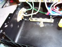
Here are a couple of pictures that show how I moved the gate resistors and added bypassing. Not "production ready" but works.
Attachments
Hi,
It depends how detailed you need the analysis. You can certainly generate HD data vs. frequency up to 100KHz at different power levels and dump the results into Excel and plut there. An HD run of the kind you describe takes less than 2 Minutes per power datapoint (including adjusting levels and pressing buttons) in my own set-up (not AP2) using a EMU 1616m.
That said, I am unsure you can derive a lot from this plot, as you can plot only either individual harmonics or THD that way.
That is a question. What is an amplifier NEVER can "just reproduce"? Have you considered this? Just like for example the clutch and gearbox never "just "transmit power".
That depends. To me a lot of things are intellectual challenges and if nothing else it keeps my mind active to work on things that will never make me a dollar and that others have dome to a level that is probably "good enough".
Others prefer to just pay.
Depends, really. I tend to focus on a lot of things when listening critically and equally often listen not critically and only start to focus on "what's wrong" if my enjoyment is impaired.
You could try doing a CSD on the Amp, at different levels up to clipping...
You must have had a different model to others. The manual I have lists TL072 as IC's mostly and they are MOSTLY followers. Still there are a lot of them. Most can be removed though.
Ciao T
We can measure a lot, but can we measure what is important? I can't measure HD from one to rated power from 0 to 100K and plot it three dimensionaly even if I had a week to goin the plots is some tool I don't have.
It depends how detailed you need the analysis. You can certainly generate HD data vs. frequency up to 100KHz at different power levels and dump the results into Excel and plut there. An HD run of the kind you describe takes less than 2 Minutes per power datapoint (including adjusting levels and pressing buttons) in my own set-up (not AP2) using a EMU 1616m.
That said, I am unsure you can derive a lot from this plot, as you can plot only either individual harmonics or THD that way.
An amp should not "voice" but reproduce.
That is a question. What is an amplifier NEVER can "just reproduce"? Have you considered this? Just like for example the clutch and gearbox never "just "transmit power".
In reality, am I really just subject to their expertise. Pay my money and shut up?
That depends. To me a lot of things are intellectual challenges and if nothing else it keeps my mind active to work on things that will never make me a dollar and that others have dome to a level that is probably "good enough".
Others prefer to just pay.
My basic problem with experienced critical listening is that human nature seems to single out one thing you can hear and focus on just that.
Depends, really. I tend to focus on a lot of things when listening critically and equally often listen not critically and only start to focus on "what's wrong" if my enjoyment is impaired.
Are there other dynamic tests that I can capture with a mic that could say why one amp is harsh, and one not?
You could try doing a CSD on the Amp, at different levels up to clipping...
Apt: I hope their power amp was better than their preamp. I got talked into trading in my Hafler kit for one. What a bad mistake. Noisey, closed in, distorted. When I peaked inside, it was a pile of 741's that were long sense obsolete by the TLO74 and none of the tricks like biasing into class A were known, never mind easily surpassed by simple discrete designs.
You must have had a different model to others. The manual I have lists TL072 as IC's mostly and they are MOSTLY followers. Still there are a lot of them. Most can be removed though.
Ciao T
I have one more 220 on the shelf too. I think it will hit e-bay soon.
I don't understand why you would up the bias. From what I understand, the L-FETS like a bit less, 110mA per or so. The 220 does have the full complementary input. But it is still a pain packaging.
Instead of reducing the PS, how about just regulating the VAS and IPS at a lower voltage? Say 40V?
Walt J recommended 225mA per device at 65V supplies, and at 450mA or so at 30V I figure it's almost class A all the way. I thought that was the jist of Nelson's comments. Anyway I'm lazy and like to reuse what I have, I even have a 1kVA stepdown transformer to power a pair.
Years ago I built a pair using Walt's AA article and figured the bias increase was the single biggest improvement (my ears were alway base metal I guess). I gave those to a friend 20yr. ago.
Not tried CSD on the amp yet. SoundEasy has this. Very powerful, but he uses the first law of Madison Av. "Take your worst attribute and advertise it" Easy it is not. I too have the emu-1616. It's input impedance on line is very low, so I had to build a buffer for the voltage divider type probes.
I was scanning through a few hundred pages of comments looking for favorite transistors that can still be bought. BC5550, 2SC970 etc. I have quite a list of low power I gleaned off various catalogs and forum comments, but not much on medium or output types, and almost nothing of FET's. A few comments of favorites and why would be helpful as a jump start.
Matched single die pairs seem to be smt and very low power. THAT has a few but they don't seem to be very tightly matched, more a packaging advantage.
A lot of the "prefered" parts are lower voltage. Most of the parts in the DH-120 for example, don't see very high voltage in operation, but I am not sure about power up and down. Is it considered safe to use 40V transistors in the IPS CM and input pair with 55V rails? Do you just figure to lose them if a rail fuse blows or some other hic-up? There seem to be very few in the 120 V range as that pushes you to the higher power devices, i.e. larger die and all that entails. KSA916 maybe?
All the BC family is selected in the same way, starting with BC107,108,109 continuing with 171,172,173... etc. Numbers for voltage, letters (A, B, C) for NF....that BC 550/560, 546/556 and 547/557 were in fact made in the same general batch, and were selected for propreties and arranged in families by sample selection later on. At the time, early 80ies, this shocked me, I suppose I expected to hear of some exotic process they used.
You can test non-destructive the inverse Base-Collector voltage with one 2-4 Mohm resistor series...
Last edited:
Walt J recommended 225mA per device at 65V supplies, and at 450mA or so at 30V I figure it's almost class A all the way. I thought that was the jist of Nelson's comments. Anyway I'm lazy and like to reuse what I have, I even have a 1kVA stepdown transformer to power a pair.
Years ago I built a pair using Walt's AA article and figured the bias increase was the single biggest improvement (my ears were alway base metal I guess). I gave those to a friend 20yr. ago.
I read both arguments, higher bias, lower bias. Back to listening I guess.
Reminds me. I have a stack on AA about two feet high. I have been through it several times, but as I learn more, more of the articles have useful info. Probably time to scan them again.
A former employer owes a debt to WJ, as it was his original Audio article on caps I read that lead me to solve a particularly difficult intermittent failure in our system. We had a problem of a Z80 doing NMI once a week or so. It was a matter of selecting the correct cap technology that fixed it.
Searching, I found I only have the first half of Jan's feed-forward correction piece. That was about the time I was getting too busy with British sports cars. Darn.
All the BC family is selected in the same way, starting with BC107,108,109 continuing with 171,172,173... etc. Numbers for voltage, letters (A, B, C) for NF.
Confusing, a BC550 is rated at 45V, a BC559 at 30, a BF469 is 250. Don't see a trend.
- Status
- Not open for further replies.
- Home
- Member Areas
- The Lounge
- Sound Quality Vs. Measurements