toshiba said:
Thanks a lot Karen !!
Please can you deliver Mr. Pass the following message : "Sorry for attacking
and chosen a strong title like this one for explaining what I have changed. I'm someone
who often likes to do something in a disrespectfully way."
As I wrote the thread, I thought, that the experts are coming up, analyze my changes
and kill them with words like : "You crazy crackpot from germany ... what you have done
can't work ...."
I didn't expect that anyone replies with words like : "Ok you are right and it's your way to do so."
But what happened ? The experts explain me the function of the original mute circuit and the
non experts announce their ordinary comments.
Sometimes it's better to find his own way.
toshiba
P.S.
I really respect the work of Mr.Pass. His amps sounds incredible.
Sure, he is one of the greatest, perhaps the greatest !
But could it be the reason, that it is forbidden to do some changes ?
Oooh, so that is what you were doing. Explaining what you had changed. I interpreted "Correcting this error should solve all problems concerning the Ono mute circuit in cloned PCB's. Perhaps other problems too ..." as if there was an error or even a problem in the circuit and that it would not work.
You are more than welcome to change anything you wish...at least I have nothing against that. I just think very few people understood your post as telling us about the changes you had made as it sounded like something else.
delay circuit
Hi all,
I make some experiments with this delay circuit, and results are interesting for me.
First, in service manual for preamp I don't see two delay circuit (only two relays) and my conclusion is that two relays are connected in series.
Second, I measure several 24V relays and resulting voltage are Von about 18V, Voff about 7V.
Third, Q25 (in my experiment 9630) start conduct when Vgs is about 3V, and this happened (if D is LED with Va-k-on about 2V) when Vcc is greater then 12V with value of R78 and R74 referred to service manual.
Where is fault? Q25 will switch off when Vcc drop at 12V. In this moment relays are already deenergised (or in same time) because Voff relays are about 7V (two in series, 14V). I try shortening Q25, and Voff (and time off) is same with and without. With this value of R78 and R74, Q25 is useless.
I connect 1k resistor parallel to R78, then Voff of Q25 rise to about 24V, and then this circuit work fine.
Maybe elements in original design have slightly differ characteristics, but my theoretically and practically point of view is that this circuit need some revision.
Regards
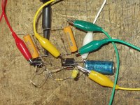
test circuit
Hi all,
I make some experiments with this delay circuit, and results are interesting for me.
First, in service manual for preamp I don't see two delay circuit (only two relays) and my conclusion is that two relays are connected in series.
Second, I measure several 24V relays and resulting voltage are Von about 18V, Voff about 7V.
Third, Q25 (in my experiment 9630) start conduct when Vgs is about 3V, and this happened (if D is LED with Va-k-on about 2V) when Vcc is greater then 12V with value of R78 and R74 referred to service manual.
Where is fault? Q25 will switch off when Vcc drop at 12V. In this moment relays are already deenergised (or in same time) because Voff relays are about 7V (two in series, 14V). I try shortening Q25, and Voff (and time off) is same with and without. With this value of R78 and R74, Q25 is useless.
I connect 1k resistor parallel to R78, then Voff of Q25 rise to about 24V, and then this circuit work fine.
Maybe elements in original design have slightly differ characteristics, but my theoretically and practically point of view is that this circuit need some revision.
Regards
test circuit
Attachments
Me too!
"Maybe elements in original design have slightly differ characteristics, but my theoretically and practically point of view is that this circuit need some revision."
Well don't leave just hanging. Nobody else can figure it out either.
Straighten us out please! I for one would like to know how to get this thing to work. maybe that's the wrong color LED since they have different voltages.
http://katalogi.iele.polsl.gliwice.pl/en/download.php?id=24064
http://katalogi.iele.polsl.gliwice.pl/en/download.php?id=23886
http://katalogi.iele.polsl.gliwice.pl/en/download.php?id=4795
http://ctlgserv.mew.co.jp/acg/cgi/mech_eng/mech_eng_pdflink.cgi?l=ds2y DS2Y-S-24V
Nominal
voltage,
V DC
Part No.
Pick-up
voltage,
V DC (max.)
Drop-out
voltage,
V DC (min.)
Nominal operating
current
mA (
±
10%)
Coil resistance,
W
(
±
10%)
Nominal
operating
power mW
Maximum allowable
voltage, V DC
24 DS2Y-SL2-DC24V 16.8 7.5 7.5 3,200 3,200 180 180 48
PerAnders does industrial electronics, maybe he can figure it out.
OH MY GOD!
"Nelson Pass = Fred Dieckmann"
"Now that sock puppet got right past us mods, tee hee"
Don't even make a joke like that, I already get trashed for using the name "Norm Thagard" the name of a very famous astronaut and audio amp hobbiest, who is friend of Mr. Pass I believe. It was such a obvious joke that I though everyone would know after one post. I believe Grey didn't and was extremely displeased.
Re: Me too!
Hi,
OK, let's start from the scratch:
D? is a regular LED with Vak = 2.5 V. There are two relays in the circuit with nominal operating voltage Vr = 24V. (the original service manual says "Q25 and Q26 are used to power the mute relays. The front panel LED must function for Q25 to turn on and pull the mute relays off").
Bottom MOSFET is irrelevant because it functions as a short circuit when the circuit is powered off.
The circuit operates as follows: When the Vunreg starts dropping, relays voltage starts dropping as well until Vunreg drops below Voff=K*Vgs(th)+Vled, where K =(R78+R74)/R78, Vgs(th) = ca. 3V and Vled= ca. 2.5V. Then the MOSFET switches off relatively quickly (transfer function knee), which switches off the relays as well. In this case Voff = ca. 12V. However, by the time Vunreg drops below Voff=12V, the relays have already reached Vdrop-out value and deenergized. Switching off relays via MOSFET Q25 is therefore useless because they are already switched off, i.e. Q25 can be left out.
If we want to increase Voff(MOSFET), we need a lower value of R78 or a higher value of R74 or to increase Vled (by placing more LEDs in series or replacing them with a Zener diode).
In this case, if we want Q25 to switch off the relays when Vunreg drops below Voff = 30V, keeping 1 LED in the circuit and the value of R74=3.32k, we can calculate the value of R78 using the following formula: R78=Vgs(th)*R74/(Voff-Vd-Vgs), R78=3*3.32/(30-2,5-3)=ca 400ohm. If we take the standard value of R78=470ohm, we will get Voff=ca 27V. It would be possible to use a higher value of Voff but, since I don't know what's the value of Vripple on Vunreg, Voff=30V seems to be the best choice here.
If anyone finds a flaw in my method, I'd appreciate their comments and feedback. Also, I apologize if my post is too long and/or too boring.
Regards
Fred Dieckmann said:[BWell don't leave just hanging. Nobody else can figure it out either.
Straighten us out please!
out. [/B]
Hi,
OK, let's start from the scratch:
D? is a regular LED with Vak = 2.5 V. There are two relays in the circuit with nominal operating voltage Vr = 24V. (the original service manual says "Q25 and Q26 are used to power the mute relays. The front panel LED must function for Q25 to turn on and pull the mute relays off").
Bottom MOSFET is irrelevant because it functions as a short circuit when the circuit is powered off.
The circuit operates as follows: When the Vunreg starts dropping, relays voltage starts dropping as well until Vunreg drops below Voff=K*Vgs(th)+Vled, where K =(R78+R74)/R78, Vgs(th) = ca. 3V and Vled= ca. 2.5V. Then the MOSFET switches off relatively quickly (transfer function knee), which switches off the relays as well. In this case Voff = ca. 12V. However, by the time Vunreg drops below Voff=12V, the relays have already reached Vdrop-out value and deenergized. Switching off relays via MOSFET Q25 is therefore useless because they are already switched off, i.e. Q25 can be left out.
If we want to increase Voff(MOSFET), we need a lower value of R78 or a higher value of R74 or to increase Vled (by placing more LEDs in series or replacing them with a Zener diode).
In this case, if we want Q25 to switch off the relays when Vunreg drops below Voff = 30V, keeping 1 LED in the circuit and the value of R74=3.32k, we can calculate the value of R78 using the following formula: R78=Vgs(th)*R74/(Voff-Vd-Vgs), R78=3*3.32/(30-2,5-3)=ca 400ohm. If we take the standard value of R78=470ohm, we will get Voff=ca 27V. It would be possible to use a higher value of Voff but, since I don't know what's the value of Vripple on Vunreg, Voff=30V seems to be the best choice here.
If anyone finds a flaw in my method, I'd appreciate their comments and feedback. Also, I apologize if my post is too long and/or too boring.
Regards
I might be silly.
When the relay activates, Vgs of Q25 is 12V and coil voltage is 24V.
When the power turns off, the relay coil acts as an inductor.
Then, the relay coil induces emf, trying to maintain the original coil voltage of 24V until Vgs of Q25 reduces down to 4V. This might happen in short time, and sudden off of Q25.
Q26 turns on the relay, the relay turns off Q25, and whole system goes off.
Am I really silly?
JH
Re: delay circuit
moamps said:Hi all,
I make some experiments with this delay circuit, and results are interesting for me.
First, in service manual for preamp I don't see two delay circuit (only two relays) and my conclusion is that two relays are connected in series.
It depends if you use two or one PCB-Supplyboard. Some DIY-Ono-Clones use only one PCB-Board and in this case you connect two Delay relais from one
40 Volt Supply rail from the regulation part. In my case i use only one PCB-Supply-Board. I think in the original
Xono-Design there are two PCB-Supply boards right ?
For practical reason (its much easier to get 24Volt Relais instead a
48Volt relais) PQuadrat (who made the
PCBs) and i for example are using the meder relais 24volt (Part-Number DIL24-2C90-63L). The coil resistens in the data-spec is 2 KOhm.
On the PCBs there is a pre-resistor R19.
The Supply-Voltage for the Relais i have measured in my case 42V without loads.
With R19=1.5 Kohm i had switching
problems. So it would be there nice if you could check that with this pre-resistor R19 and two Relais from one PCB-Supply and one regulation.
Thanks a lot.
Is in this case a Resistor R19= 3,3 Kohm
i observed no swichting problems since them. But it could be in my case a problem with a faulty R77 and/or Q25
(see my other thread swichting problem
aleph ono)
Re: Re: delay circuit
TheMyxin said:moamps said:
So it would be there nice if you could check that with this pre-resistor R19 and two Relais from one PCB-Supply and one regulation.
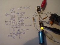
Hi,
I'm not sure how look your pcb, and where you place R19. I made for you quick test and circuit below work just fine. If your schematic is differ, please put it here. My suggestion (revision) is changing R78 to 470ohm (q25 will switch off about 27V).
If you are trying this circuit before correcting error with direction of D11 (earlier posts), maybe is your Q25 burned. R77 can't be burned.
Regards
Attachments
Re: I might be silly.
Hi,
you aren't silly.
Acting relays like inductor is not important here. Back EMF is supressed with D11. Look my measurement at circuit one post up.
Regards
jh6you said:When the relay activates, Vgs of Q25 is 12V and coil voltage is 24V.
When the power turns off, the relay coil acts as an inductor.
Then, the relay coil induces emf, trying to maintain the original coil voltage of 24V until Vgs of Q25 reduces down to 4V. This might happen in short time, and sudden off of Q25.
Q26 turns on the relay, the relay turns off Q25, and whole system goes off.
Am I really silly?
JH
Hi,
you aren't silly.
Acting relays like inductor is not important here. Back EMF is supressed with D11. Look my measurement at circuit one post up.
Regards
and it relay relay works.........
Go look at post number two in this thread. This is a relay driver with two transistors. How hard can it be to understand? One 24 V relay will handle the voltage the coil will see. Two of them would be in parallel if the schematic is correct. It shows one only channel and no coils in series are shown.
"Vunreg drops below Voff=12V, the relays have already reached Vdrop-out value and deenergized."
Gee..... the data sheet said the drop out voltage for the 24 volt relay is a minimum of 2.4 Volts. The voltage for a blue LED is 3.5 to 4 volts I believe.
http://ctlgserv.mew.co.jp/acg/cgi/mech_eng/mech_eng_pdflink.cgi?l=ds2y
I was being very sacastic about being straightened out on how it works. The fact that I think I explained it on the second post of the thread and posted the data sheets might have been a clue. The next time you rocket scientist want to deconstruct a simple circuit, at least READ THE DATA SHEETS. Somehow I think Mr. Pass is smart enough to design a relay driver and careful enough to draw the schematic correctly. This whole thread is one of the silliest things I have ever read.
Re: and it relay relay works.........
OK, Dickmann,
so I didn't get your sarcasm. I'm just a B.Sc.E.E. and I don't get it when people get all metaphorical or whatnot on me (in a foreign language too) when I'm trying to discuss some serious issues. Reading your posts, it was only clear to me that you had no idea on how the thing works in practice (you also used to claim relays were 48V, remember?) so I truly thought you needed some 'straightening out'. Now I don't know why I even bothered as you can obviously think of no other argument besides Mr. Pass-knows-best mantra (with all due respect to Mr. Pass) that you keep repeating post after post.
"Gee..... the data sheet said the drop out voltage for the 24 volt relay is a minimum of 2.4 Volts. The voltage for a blue LED is 3.5 to 4 volts I believe."
Now, you could also benefit from reading data sheets more carefully as this one clearly says that the MINIMUM is 2.4V. I don't see it anywhere written what's the maximum. Do you? I'm telling you that IN PRACTICE Vdrop-out is about 7V for a 24V relay; blue LED doesn't change anything. Last time I checked, my instruments were working perfectly well.
Unless you can prove me wrong, I'll keep claiming that there is a flaw in the circuit design - Q25 switches off too late.
Truly yours,
Rocket Scientist
Fred Dieckmann said:
I was being very sacastic about being straightened out on how it works.......
OK, Dickmann,
so I didn't get your sarcasm. I'm just a B.Sc.E.E. and I don't get it when people get all metaphorical or whatnot on me (in a foreign language too) when I'm trying to discuss some serious issues. Reading your posts, it was only clear to me that you had no idea on how the thing works in practice (you also used to claim relays were 48V, remember?) so I truly thought you needed some 'straightening out'. Now I don't know why I even bothered as you can obviously think of no other argument besides Mr. Pass-knows-best mantra (with all due respect to Mr. Pass) that you keep repeating post after post.
"Gee..... the data sheet said the drop out voltage for the 24 volt relay is a minimum of 2.4 Volts. The voltage for a blue LED is 3.5 to 4 volts I believe."
Now, you could also benefit from reading data sheets more carefully as this one clearly says that the MINIMUM is 2.4V. I don't see it anywhere written what's the maximum. Do you? I'm telling you that IN PRACTICE Vdrop-out is about 7V for a 24V relay; blue LED doesn't change anything. Last time I checked, my instruments were working perfectly well.
Unless you can prove me wrong, I'll keep claiming that there is a flaw in the circuit design - Q25 switches off too late.
Truly yours,
Rocket Scientist
The data sheet is for the one Pass is using.
I will be glad to talk to you after you read the data sheet. It's a little hard to discuss theory when you don't have the data. You can write equations you want but plugging values for the variables in off the top of your head won't tell you much.
12V -3V is 9V which is a hell of lot more than 2.4 volts the top fet will mute the relays long before the 2.4 volt drop out voltage. I can hardly wait till will audio circuit..........
Re: Re: Re: delay circuit
moamps said:
Hi,
I'm not sure how look your pcb, and where you place R19.
I will post the Thread where you can see the photo of the Alpeh Ono Boards from the top. R19 is the resistor between the Relais and the MOSFET on the Ono-Boards
http://www.diyaudio.com/forums/showthread.php?threadid=8135&highlight=Ono
The PCB-Supply is on the right PCB and
feeds direclty R19 and the Relais.
As i understand correctly R19 is in the cicuit-scheme directly behind D10 and before the coil of the relais. So the
coil restors and the pre-resistor r19 build a voltage dividivier for the Relais.
correcting error with direction of D11 (earlier posts), maybe is your Q25 burned. R77 can't be burned.
No i have correct the Direction of D11 but perhaps Q25 was really damaged
because i have made my first tests
without the correction. So know i have
a new R77 and new Q25. R77 was at
the start only 0.25W and now has 0.6W
(i was afraid that 0.25W is to low !)
Regards
Referring to the schematic by Fred on the first page of this thread, there are a couple of comments which might shed some additional light on the circuit.
The diode from Gate to Drain of Q26 is there to prevent the Gate of Q26 from getting more positive that its rating, otherwise ultimately the Gate would be at the + rail value. When Q26 conducts, its Drain goes toward ground until it hits about +3 V,
at which point the current starts flowing through the diode.
Often this circuit has been implemented differently around Q25, where a supply regulator is being used. The Source of Q25 is attached to the positive unregulated supply, and the Gate is attached (through a resistor) to the regulated supply. When the difference between unregulated and regulated supply becomes less that the Vgs of Q25, the relay is shut down. This makes an excellent sensor which turns the relay off when there is no longer enough unregulated supply to hold regulation, the "off" condition corresponding nicely to this.
Re: Re: Re: Re: delay circuit
Hi,
R77 is 750K resistor, current thru them can be in worst case I=V/R=40V/750000=ca 50uA. Power dissipation on R77 is then P=V*I= 2mW !!!!! , 0,25W is more than enough. Preresistor R19 can be between zero (maximum heating of relays, Q25, Q26) and about 1k (from my experiments).
Regards
TheMyxin said:
Hi,
R77 is 750K resistor, current thru them can be in worst case I=V/R=40V/750000=ca 50uA. Power dissipation on R77 is then P=V*I= 2mW !!!!! , 0,25W is more than enough. Preresistor R19 can be between zero (maximum heating of relays, Q25, Q26) and about 1k (from my experiments).
Regards
I guess that settles it?
I guess that means that it works as drawn....... imagine that! I suppose the threshold for Q25 turning off could be very easily set for a higher supply voltage with a smaller value for R78. That that seems to be a concern for a couple of people....... Also, I guess if one did not have as much supply voltage to play with that a 9 volt zener clamp gate to ground for Q26 instead of the gate to drain diode could get you another 3 volts to play with across the relay coil.
I think it is a very nice circuit for using left over mosfets from matching. Adapting for bipolars should be very easy too. Want not waste not. I can't understand the confusion over it once one knows the relay threshold voltages.
- Status
- This old topic is closed. If you want to reopen this topic, contact a moderator using the "Report Post" button.
- Home
- Amplifiers
- Pass Labs
- Sorry Nelson, but I have found an error ...