Hello (and "Guten Tag") invisible force!
I guess you mean this post:
"Also titled: are you sure it's the laser going bad?
Users of these fine machines and also related models using the same mechanism based on the KSS272A laser block, that have problems with their machines readong some discs, may find this of use:
Two problems that often crop up that look like the laser may be going bad, but are NOT laser related at all, so be sure to check:
1) One or more of the following happens:
- Inability to read the TOC, after which the CDP stops with '0' on the track count display and with the track display off. In these cases the CD may not respond to the keyboard any more until it's switched off and back on again. Sometimes the error goes away after the CDP sits switched off for a while.
- Sudden failure to red the disc (often with some prior skipping), if eject is pressed immediately, the disc will still be spinning and ends up 'grinding' on the tray.
- CDP starts skipping periodically but not at the same rate as the spinning of the disc. Ejecting may also produce the 'disc grinds in drawer' effect.
The cause of this problem are cold solder joints on the mechanism controller, the two-sided board fitted to the actual bottom of the mechanism. In particular, in most cases it's an intermittent contact in the small 2-pin connector, closest to the front panel. This carries the supply voltage for the BSL spindle motor driver chip. The actual symptom has to do with this chip losing one or both supplies resulting in uncontrolled spinning or failure to spin. It is not easy to spot until it really becomes bad because the servo system can correct this. At some point, it cannot any more and the motor either 'runs away' spinning like crazy - this is the 'CD spins in drawer' case - or stops completely - this is the 0 track, no track display case. The motor is so silent even if it spins like mad that it's very hard to hear, unless the case is open and you can see it happen. In some cases it can even start spinning on it's own just sitting there without a disc, or with a disc but in a stopped condition.
The reason it happens is that the driver chip heats the PCB which results in cold solder joints on the connector nearby (even more susceptible because of the cble flexing when the disc is loaded or unloaded) and the chip itself. In these cases it is advisable to carefully re-solder the whole board and then wash it in isopropanol or PCB cleaning spray (resoldering requires putting liquid flux on the pins of the chips etc. and leaves a residue after it is done). Remember to check and resolder both sides of the board! This is a precision double-sided affair so be sure you know what you are doing. The laser head flat cable needs to be removed, careful, this is static sensitive!!!!!
The above problem pertains to all CDPs with the same mechanism, that would be CDP-X303, 339, 505, 559, 707, 779 and corresponding Japanese model designators.
The following problem is speciffic to the CDP-C779/707 (and Japanese market equivalents):
2) Nasty skipping on damaged discs that should normally be readable at most with sound degradation or muting, and are on other machines. In advanced cases it may skip backeards and just keep repeating the same part of the track ad infinitum.
The way to check for hard errors and susceptibility to them is to load the suspect disc and try to go fast-forward through it. In this case the servo system is more susceptible to losing the track, which can be seen in the time display - time is lost and more often, skips backwards a few times when a hard error is encountered, after a few times it can then skip forward by several or more seconds - this is common to most implementations using the CXD2500 decoder chip and Sony CPU to control it, the CPU detects repeated problems and tries to skip 'over' the problem area. Repeated skipping backwards only to repeat it again is a sign you have this problem - in fact, it is highly probably all X779/707 have it, but doe to tolerances, it may be more or less visible.
The actual problem has to do with what must be a manufacturing flaw. In particular a resistor with a wrong value has been used on the digital PSU board. The reason the problem happens is instability of the Vee negative supply (incorrectly labeled as 1.7V in the service manual, corrected in a supplement, should be 3.7V) under load. It is easy to check for this problem by using a voltmeter between the chasis and the copper heatsink on the digital PSU board edge closer to the front panel, righ next to the filter cap. If you see 3.1-3.5V, your CDP has this problem. It is present in the 4 I have here, and because the wrong value of the resistor is clearly documented in the service manual, it is likely they all have it.
The Vee negative supply is generated by a simple linear regulator, 2 transistors and a zener diode for reference. The clue is that the zener diode D959 is rated at 4.3V but the voltage on it is usually below 4V. This is so because the resistor R961 feeding it is way too large at 4.7k - the current through the zener diode is far too low to establish proper zener diode operation. The result is that D959 operates at a working point where it's internal impedance is very high and unstable, making Vee very variable under load.
When the CDP encounters an error, it needs a much larger current to control the laser head, and demanding it from Vee results in collapse of the Vee. Because there are a number of circuits using Vee (including the spindle motor mentioned in the problem above!), a large amount of the drive electronics starts operating improperly at that moment, the servo circuits lose control of the head and reset, which incidentally makes the head skip uncontrolably backwards a bit, resulting in the nasty skipping.
The solution is simple: change R961 from 4.7k to 820 ohms.
There are a few optional steps that can be taken to further improve things, including long term reliability:
Changing C963 from 2200uF/10V to say 4700uF/6.3V additionally improves Vee stiffness and stability. Often just doing that without the R961 fix reduces the skipping problem, clearly showing Vee is the culprit.
The 5V output is invariably a bit high, around 5.2 - 5.3V. It can be trimmed closer to 5.1V as stated in the manual by soldering a 27k resistor in parallel to R956, on the bottom side of the board. This is important because the laser head is supplied with this voltage, so overvolting is not at all desirable here. The 6V voltage (incorrectly labeled as 7V in the manual!) is not that critical and can be left alone."
Found the parts mentioned in XA7ES manual (It does not seem to be PSU but "Drive -7V REG") but to my limited eye and knowledge, I do not see an equivalent curcuitry in the X5000. But I am sure somebody will do!
Hello salar,
I recommend :
1. With my player problem was the connector from the laser pickup to the servo board, see http://www.diyaudio.com/forums/digital-source/226288-sony-cdp790-kss240-restoration-project.html, for cleaning the wide flexible thin connector and more (bad solder points..)..
2. take an oscilloscope and watch the +-7 Volts when player is out of control, does voltage collapse - if so change the electrolytic caps nearby the 7V regulators..
3. With my player spindle drivers BA 6297 got very hot..I heatsinked them with little heatsinks made for RAM Modules for PC (thermal adhesive tabe to glue them).
4.take a close look /change the C1 cap (100yF) close to the laser..
hope this helps...
Hello Invisible Force (may it be with you)
I will look at the connector. Where do I shorten the laser pickup to prevent electrostatic breakdown?
There is no +/-7Volts circiutry as far as I can see.
As reference please watch X5000 Service Manual:
http://bildarkiv.hififorum.nu/kasra/kyl/asdf/sonycdp-x5000manual.pdf
I will look at the connector. Where do I shorten the laser pickup to prevent electrostatic breakdown?
There is no +/-7Volts circiutry as far as I can see.
As reference please watch X5000 Service Manual:
http://bildarkiv.hififorum.nu/kasra/kyl/asdf/sonycdp-x5000manual.pdf
I really don´t know. You have to follow the track on the Kapton flex cable to find out.
As to the other topics. There are +- 7 volt going to the servos controlling the sled and spindle motor and focusing. Those voltages are handled by ordinary 7807 and 7907 on the audio board. The zener diode mentioned (Thevintageknob) as underbiased is part of the -15 volt going to the fluorecent display. It is a 3.9 volt zener 400mW (D976). How this can cause the skipping I am honestly not able to see.
As to the other topics. There are +- 7 volt going to the servos controlling the sled and spindle motor and focusing. Those voltages are handled by ordinary 7807 and 7907 on the audio board. The zener diode mentioned (Thevintageknob) as underbiased is part of the -15 volt going to the fluorecent display. It is a 3.9 volt zener 400mW (D976). How this can cause the skipping I am honestly not able to see.
Last edited:
Thanks Dacen. I have one spare KSS-274A but I wanted to ask instead of unpacking the spare and checking myself.
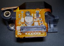
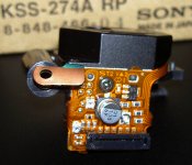
Well, I looked at the spare laser some minutes ago - no shorted pins at all (!) to prevent the diode from electrostatic breakdown. Loks like on the photo posted above.
Only the usual advice to work on a grounded workplace and bench.
From my other players (Toshiba XR-Z70 - OPH-32 and Nakamichi OMS-5EII - KSS-123A) I know that shorting the laser diode to ground with a blob of solder at dedicated lands was usual.
I do not think that diodes almost 8 years later were less prone to electrostatic breakdown? Seems to me more of a sign of the decline of Sony: Instead of adding a blob/bridge which might cost time (and probably has to be done by hand) they simply left it to the gods of electricity. Imagine how many service technicians wrecked the KSS-274A wearing wool jackets and synthetics, not being aware that they already had to be
grounded while unpacking the freshly arrived spare laser.
I guess, i will be on the safe side, when shorting pins 23+24 together with pins 1+2 of the RF-Amp M52104FP before disconnecting...?
I want to do this to remove the laser, so I can resolder everything on the servo board faster and easier.
You wrote tbefore to take care before removing the flex cable, thanks for that . Another useful advice missing in the service manual...
I remenber a densely packed Panasonic DV-camera once, with many flex connectors I modded once.
Still, all connectors were described and how to safely disconnect...
Last edited:
I know this guide, very good and helpful.
But with the CDP-X5000, there is no adjustment possible besides adjusting physical height of the laser.
(Called "Skew Adjustment" see page 11 of the service manual)
Just finished resoldering te servo board. 9/10 of the time was spent to remove shorts between IC-pins caused by the solder iron tip. With 1,5mm it was too large. At least, the parts now have passed a heat-related stress test
I did not resolder the big IC´s like servo and system control but the rest, including connectors.
No difference. Still glitches when being cold
BUT: I was not able to resolder the BSL board for the spindle motor drive.
Ridiculous: Sony used fancy, pro-looking Allen screws for the cabinet, but Philips srews everywhere else.
Because of this I have to apply too much vertical force to unscrew the metal base plate of the BSL-board.
This would not have been a problem at all if Sony had used Allen screws for crucial parts!
But no cold solder joints on the servo board (flex cables were unplugged and replugged) and a big surprise:
Laser in my Sony CDP-X5000 is KSS-273A, not KSS-274A as stated in the www and service manual. But I guess both are identical...
Last edited:
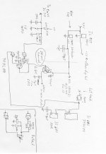
Here is all the modifications I have done so far. Works perfectly so far. The 1n4148 and 10uF capacitor plus resistors is a delay circuit when the lid switch is opened. If this delay is not present the spindle motor does not stop spinning when lid is opened while playing. In other Sony players with fixed pickup and a conventional drawer this function (cut power to the laser) is handled by a mechanical switch and not a transistor. This is only a double security to prevent hazardous radiation from the laser to the eyes. I will certainly have a go at the zener biasing. It is very easy to do the test and the zener is only burning 13 mW with the 3.3 Kohm so no harm can be done with lowering to say around 800 ohm. Will report in a while.
I bought my player from a man in Singapore because he was experiencing skipping from time to time. I have always been almost certain that the skipping was not caused by a bad laser, so we will see how this ends up.
I bought my player from a man in Singapore because he was experiencing skipping from time to time. I have always been almost certain that the skipping was not caused by a bad laser, so we will see how this ends up.
Attachments
Last edited:
How is pin 45 (lid switch) of system control IC cxp84124 related to pin 17? (spindle motor mute). Could Q104/105 cause the glitches?
In the datashheet of the Mitsubishi voltage regulators M5F78M07 and M5F79M07, 0,1µF are recommended at the voltage in/outs. Sony did "only" use 2200µF caps at the regulators outputs. Did add 0,1µF,
but no difference.
In the datashheet of the Mitsubishi voltage regulators M5F78M07 and M5F79M07, 0,1µF are recommended at the voltage in/outs. Sony did "only" use 2200µF caps at the regulators outputs. Did add 0,1µF,
but no difference.
Page 18 in the schematics (spindle mute). I had to delay the lid switch in the nand gate just to give the spindle time to stop. There is a kind of brake function taking place when you open the lid. How that is done I don´t know. Maybe just reversing the polarity for a short while. If the laser is shut down immediately the spindle continues to spin slower and slower until it stops by itself, that is no braking function taking place.
Hello dacen!
Can this cause the playback glitches? Noisy input? Something triggering it every 2 seconds?
You added a nand gate. Did the motor not stop when you opened the lid?
Mine does. All button functions work perfectly.
Could there be something we have overseen in the circiutry of the sled drive?
How (and when) is the sled motor triggered?
All the best,
Salar
I did resolder the BSL_Board (The board of the spindle motor) and clean and grease the mechanism.
I could not disassemble the board because of stiff srews. Because of this, the only parts I could not reach were the diodes H11 and H12.
Again, no cure, problem persits.
But I do not think it is the BSL_board because something very intersting happened:
In order to spread the grease over the rail, I did play a CD in Fast Forward, and before it reached the end, played it in Rewind, until it reached the beginning of the CD.
Switching in Play-mode directl, the glitches were audible immediately.
But going to stop, then to play, (The disc now repositioned itself) it now takes about two minutes before the first glitches are audible.
So I guess the sled motor places the CD in a better centered, horizontal starting position after stopping, but in a bad, more off centered position after Rew/FFWD.
Conclusion: The glitches must be caused because of bad interaction between laser coils and sled motor.
"E-F balance" as well as "FCS-Bias" can be trimmed on the laser. I gues FCS Bias is Focus?
Does anyone know wether E-F signal is used for driving the sled motor? I guess not because it E-F signal keeps the laser centered?
Last edited:
...Does anyone know wether E-F signal is used for driving the sled motor? I guess not because it E-F signal keeps the laser centered?
E-F refers to the two photodiodes that monitor the two side-images of the 3-beam system. Pds A,B,C and D monitor the central image, and are used for focus and data extraction.
Essentially, a difference in brightness between the two side images results in a difference in signal amplitude from the the E-F pds. This difference is processed and becomes the radial error signal.
Radial error is corrected by applying this signal to the tracking coils in the head and to the sled. If the voltage across the tracking coils necessary to keep the image centralised rises beyond a certain level, then it drives the sled.
Considering that the head must move radially at a steadily decreasing velocity as it progresses through the disc, I guess there is some compromise with bias, because without some offset or bias the head would remain stationary with respect to the disc whenever correctly positioned, whereas it should ideally keep moving at a correct velocity.
I suggested early in the thread that the unusual sled arrangement in these players might mean that some parts or circuit elements are closer than usual to operational limits.
I gather that the laser mech is standard, including the sprung rack that usually drives it. If the electronics are also standard Sony issue, then how have they taken into account the different dynamics of the fixed-head system?
If you can monitor the voltages across the sled and tracking coils whilst playing, when it's working good and when it isn't, you may be able to see what's going on.
I'm really struggling with a CDP101 with a similarly infuriating fault. Any problem in controlling the head appears everywhere pretty much simultaneously, so it's hard to tell the difference between cause and effect.
I remember going to a Sony showroom on Champs-Elysées several times to listen to a CDP-101 back in 1982, maybe half a year before CD was introduced in Europe... Saw the last in September 2012 in a shop called "Haus der Musik" in Bonn. Strange shop.They do not sell used HiFi officially, but all goods look a bit outdated. Like they bought then 20 years ago and wait patiently for customers since then. CDP 101 just looked like it stood there for 30 years, im mint condition. You could contact them, I would not wonder if it stil was there.
In my Nakamichi OMS-5EII, I can monitor the low frequency error Signal and how it vanishes and rises again, after the sled catches up.
I will compare the circuitry leading to pins 26-30 of CXD2515 and leading from pins 2 &100 between CDP-X5000 and CDP-XA7ES. They carry the error signals. I will also check for E-F balance, manufacturing errors -wrong resistor/capacitor values on pcb - and report back...
Checked E-F balance:
O.K.
Checked the circuitry driving the sled motor, i.e. everything connected to pins 26-30 and ins 2 & 100 of CXD2515 coming from laser and leading to BA6297:
Did not find wrong resistor values, but could not check capacitor values, the SMD capacitors do not have any markings!
Compared sled circuitry of CDP-X5000 with CDP-XA7ES: Circuitry between CXD2515 and BA6297 seems to be absolutely identical in both players.
Resistors and capacitors even share the same reference numbers in both service manuals .
Carefully resoldered pins of CXD2515.
Fault has not changed:
The player has audible glitches when being cold and playing a disc. Heating it up with a hairdryer for a minute or having it play for more than half an hour cures the problem.
I guess I have done everything besides adding capacitors of higher values in the powersupply and carefully resolder the laser´s RF-Amp.
Will do this next.
I do not think that the "Fixed Pickup Mechanism" takes the circuitry to its limits. 70% of the weight / mass the sled motor has to move is from the brass stabilizer fixing the disc.
I tried a lighter stabilizer made of aluminium weighting only the half. No difference at all...
All the best,
Salar
Last edited:
Did replace the 16V & 25V 2200µF with 4700µF/25V Low ESR caps.
The glitches are still there but at least it seems the time they disappear has become shorter.
Does anyone has a service manual of a player using CXD-2515 / BA6297 which as a regular transport? Would like to check how an ordinary sled motor is adressed.
Roundup:
Resoldered the servo board, BSL board, Laser board to exclude cold solder joints. Only parts not resoldered are diodes H11/H12 on the BSL board because they are out of reach.
Checked E-F balance and eypattern they are ok.
Swapped 2200µF caps on the PSU board and audio board to 4700µF.
Bypassed M5F7XXX voltage regulators with 0.1µF caps as recommended in the datsheets.
Servo circuitry of CDP-X5000 and CDP-XA7ES seem to be identical.
Raising the caps capacitance seems to have improved things a bit.
If anyone wants to replace the caps: They must be of exact the same size as the original caps or the top plate assembly will not fit.
Last edited:
One last - and I guess Important - addendum:
As I wrote in post #154, playing a disc in FFWD or Rew and going back to play without stopping will make the player playback any CD with glitches. But this will also happen when a disc ist played in "Repeat" mode. Also in repeat glitches will be there from the beginning.
But when the player is stopped after playing a disc and then the play button is pressed, the glitches will appear after about 2 minutes.
So I guess sled and laser optics reposition themselves in a perfect radial starting position when the player ist stopped and then start to drift apart while playing (and as long as the player is cold) .
Without stopping, this drift/misalignment is audible from the beginning.
I guess the errors come from the fact, that the circuitry for the sled sled control allows too much play. As a result the radial laser coils work too much off-centered at the limit.
This is why it takes about 2 minutes
until the first glitch is audible when laser and sled had the chance for repositioning themselves.
But it must be possible to make the sled motor to react to radial error/offset of the laser coils much sooner? I guess, it is a simple DC-Offset gained from the driver for the radial laser coils?
Can this offset signal be modified somehow?
Last edited:
The relationship between sled and radial motor must incorporate some delay, because once the sled begins to move, the tracking motor must move in the opposite direction. Because it's a tuned circuit, the effects of any adjustment are likely to be a bit complicated. Watching a Sony sled with a linear motor would be funnier if it wasn't mine. Much of the time it behaves as you imagine it should, but then for no apparent reason sled and radial motor excite each other into mutual oscillation. Not a fault AFAIK, as the player carries on playing.
Improvement from larger caps may be because of short-term power requirements associated with your fault. Can you detect a significant voltage drop in the supply to the motor drivers or servos when the fault occurs? How much difference has the change made, exactly? Has it's period halved?
As Sony notes in its manuals, some serious equipment is required to reveal the complexities of the control system, but a reasonable approximation is generally good enough becauase there is a fair margin of error, they say. Early machines had many adjustments and test pins, later ones hardly any. In my limited experience, faults can rarely be rectified by adjustment anyway. Nevertheless I'm still uncomfortable about the moving spindle idea.
Hypothesis #278: Spindle and disc together form a gyroscope that is supported and moved from one end. Jogs of the sled drive tend to throw the spindle and disc into a sideways tilt. Once clearance runs out, the spindle bearing tends to grab at each jog. This is a cumulative effect that resets itself only when the disc stops rotating. When cold, it's enough to slow rotation sufficiently so the player runs out of data before the spindle motor corrects rotation speed.
Why does my Sony fixed head machine work OK when frozen?
Hypothesis #283: condensation on the lens.
Hypothesis #285: ice in the head or elsewhere, from frozen condensate.
#286: stiff cable to spindle motor.
#289: stiff two-axis hinge/spring in head. Possibly a contributing factor in your own "drift" theory, which raises the question of why it should only happen when cold. A stiffer spring would mean a higher voltage to the tracking coil for a given movement, resulting in a sooner triggering of the sled which, if it moves the same distance as usual, may move further or faster than the coil can track back. I don't see how this would be temporarily relieved by a reset unless the power supply is fundamentally inadequate in such a way that bigger caps merely delay the onset of the problem. Stiffer motors demand more current. Perhaps there's a starved zener reference somewhere?
- Home
- Source & Line
- Digital Source
- Sony X5000 troubleshooting