Four 500 Ohm pots in second kit !
The boards from my 1st kit are populated with the resistors, caps & pots, but have been languishing in the cellar for months.
Seeing this post got me to check the pots. Seems the store sent 500 Ohm pots with Fairchilds.
The second kit has Fairchilds with four 500 Ohm pots, no 5k Ohm pots!
Yup, if you're using the fqp parts, you'll likely need the 1k pots to get to the higher/lower Vgs as compared to the Toshiba parts.
The VFETs are not matched across polarities (n,p), so yours will work fine.
The boards from my 1st kit are populated with the resistors, caps & pots, but have been languishing in the cellar for months.
Seeing this post got me to check the pots. Seems the store sent 500 Ohm pots with Fairchilds.
The second kit has Fairchilds with four 500 Ohm pots, no 5k Ohm pots!
I have completed voltage measurements and attached the results. I am concerned that the rail voltages, G-T6/T8 (approx 33 Volts) are a bit too high. My transformer is a Toroidy with 22V secondaries. My wall voltage is 123V, which is higher than the 115V toroid design. I am using the universal PSU rectifier board with fast Schottky diodes. I changed P3/P4 to the recommended value of 1K for use with the Fairchild MOSFETS. I believe the 9V measurements shown in the results are due to the higher resistance of P3/P4.
I proceeded with biasing up the front end and was able to achieve 1.5V across R5 and R6, with a T18/Gnd output voltage around 0.1 to 0.3 volts. My question now is, should I proceed to installing the VFETS with the higher rail voltage or correct it? If I should need to lower it, how do I do so?
Steve
Attachments
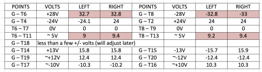
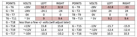
Your 9V readings are from the 1K P3/P4 pots.
My guess is that the rail voltages will drop a bit with a load though may still
be higher than 28V. The IRFP240/IRFP9240 mosfets will run a bit hotter but I suspect
should not be a problem. If it ends up higher than you like, you can
burn a bit of voltage by increasing the resistance in the CRC supply,
but I personally would give it a go as-is.
Hopefully others will chime in as well.
I proceeded on to Part 4, and all WAS going good. Started with the left channel only, and voltage across R32 and DC offset at output were low. Started the incremental increasing and all was going well. Around 80 mV across R32, I accidentally started to change P3 instead of P1 as I was supposed to. Now things went bad. Started to change P3 and P4 to compensate, along with P1 and P2. Decided to start over but maybe it was too late. Turned P3/P4 fully counterclockwise and rebiased front end. But now I could only get 6 mV across R32, no matter how I adjusted P1 and P2. The VFETs were cold. I think I cooked a pair of VFETs. Was there a proper procedure for starting over when things go wrong with the VFETs installed?
I went on to bias up the right channel and everything went fine. It is running with 100 mV and about about 5 to 10 mV offset at the amplifier output. Question about this working channel. R5 and R6 drops are about 1.43V each. However, the DC offset on the front end (T18 to Gnd) is now about 6.3 volts. Is this acceptable and just the result of biasing up the VFETs? Do I dare adjust P3/P4 at this point?
Please advise what I should do from here. A one channel amp wont bring very fun listening.
Steve
UPDATE:
Had the assistance of Anand (nycavsr2000) on the phone and he diagnosed my problem after measuring a few voltages: regulator Q13 was blown. Replaced it and all is well!
My question remains, after everything is stable, are there any voltages I should check and make further adjustments if they are out of range? Looks like R5 and R6 may have dropped a bit from 1.5V during the VFET biasing. And is the DC offset at T18/GND still relevant?
Steve
Hey Dennis:
My T-18-GND values were about 2.5V and 6.2V, while R5 and R6 were about 1.48V. I have now figured out how to correct the T-18-GND values. I first reduced both of the P1/P2 pots a bit. Then I snuck up on 1.5V by tweaking P3/P4. The big issue is that those two pots are extremely sensitive. So sensitive that just barely touching them with the screw drive blade can change the values by 50 to 100 mV! I have 3 meters, 5 would have been better.
Steve
I threw a bit of a tanty trying to set this amp up a few months ago and mothballed it. Yesterday I pulled it out again to finish off one side. After attacking this amp fresh - I found these steps helped immeasurably:
1. Ensure that you do the proper DC offset setup properly and thoroughly before installing the VFETs,
2. Once the VFETs are in - be prepared for the setup to take a while (all day if need be!)
3. Use three multimeters - I had my one good one, plus 2 imported cheapies. Connect the good one to your speaker terminals , one other one to your ground-T18 point, the last one across R32.
4. Aim to set your R32 100mV level first by using P1 & P2 adjustments.
5. Check that your 1.5V across R5 and R6 are still good - these wont change markedly by the following setup procedures.
6. Tweak the adjustments using P1-P4 - but with a focus on P3 and P4. The P1 and P2 adjustments will quickly re-adjust your R32 voltage (should that drop by a few volts).
7. I dont know if this is correct - but after I dialled in the R32 voltage, I then focused primarily on the speaker terminal DC offset. Once I had this close to 0v, I then fine tuned by adjusting all pots with micro-tweaks (and taps to loosen the spring tensions) to try to keep both voltages close to 0.
8. The voltgae between T18 and ground was the hardest one to nail down. At the end however I had 99mV on R32, 18mV on the speaker terminals and 34mV on T18 - however the latter was the only one that was fluctuating. In the end I was only adjusting this reading by tweaking the pots.
9. The T18 measurement is extremely susceptible to heat changes. So at the last stages of adjustment (or preferably, sooner) do these adjustments with the lid ON - otherwise you will try to set (with the lid off) and the readings start taking off about 10 minutes after you replace the lid. ensure you have a small screwdriver that you can poke thru the lid.
I got it in the end but I will double-check and re-calibrate both sides once I have the time to get back to this amp. I had the one channel running for a while and I can tell this will be so worth the effort.
Slimecity,
Thanks for documenting your final biasing procedures, much appreciated. My colleague “sledwards” above went through something similar and it literally took him all day. It is nice to know that even with VFET builders located several ponds away...basic physics doesn’t seem to change!
6L6/Pass/others,
That being said, I do have a question. This kit is shipped with the single turn pots. Any advantage/disadvantages to this type vs, multiturn Bourns equivalents?
Best,
Anand.
- Home
- Amplifiers
- Pass Labs
- Sony vFET Illustrated build guide