Without the VFETs installed the feedback loop of the amplifier is not closed, so T18-GND will never be perfectly stable. The behavior you're seeing is normal. Just breathe/blow on the frontend FETs and you'll see a drift. (This has been discussed before).
Remember, the drops across R5 and R6 should settle at 1.5V after warm-up. And more importantly, after setting the bias voltage for the VFETs with P1 and P2, you will have to check the frontend bias again! All four pots interact with each other! You should only install the VFETs after everything (frontend and VFET gate bias) is set up correctly.
Good luck!
One quick question regarding the IRFP240/9240, whether these need to be quad matched or at least pair matched in NN or PP as I believe getting them matched in NP is pretty difficult. Can I just go ahead and use some closely matched NP if possible per channel? And this NP of one channel may not be closely matched with the other NP of other channel!
Matching NP is not really feasible; the Vgs difference between the N and P parts is pretty large.
I personally wouldn't worry too much about it, but if you like, you can measure Vgs of the parts at ~1A and select NN and PP pairs.
Thanks Dennis, I will just go ahead and use my stack of available N and P mosfets and not much worry about the matching being closely
")
One quick question regarding the IRFP240/9240, whether these need to be quad matched or at least pair matched in NN or PP as I believe getting them matched in NP is pretty difficult. Can I just go ahead and use some closely matched NP if possible per channel? And this NP of one channel may not be closely matched with the other NP of other channel!
these are "just" cascodes - no need to match them at all
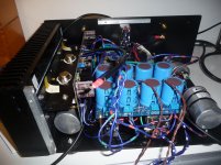
My build is getting nearer to being complete. I've used individual PSU's per channel, it all barely fits.
Although there are still a few issues. After warmup. The right channel measures 1.7V over R5/6 and the other measures 1.5V. What the best way of getting this turned down?
Also the first time I connected the speakers up, the right channel first played, then slowly got distorted during warmup and then went silent. I immediately turned the amp off, as I had no meters attached and couldn’t see what had happened. However, I’ve not been able to reproduce this since, so not sure what kind or how much of an issue this is.
Currently all vitals, like ouput DC, voltage drop over R32 and temperatures seem stable. Are there any other things I can check, I noticed there was 2V at T18, is this expected?
An externally hosted image should be here but it was not working when we last tested it.
Last edited:
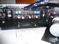
Found the post below by Dave. which put me on the right track to fine tune the front and back-ends. All seems stable now and voltages mirrored on both channels.
The amp already sounds wonderful on test speakers. Happy days!
The amp already sounds wonderful on test speakers. Happy days!
When I had the amp up and running (and at temperature) I redid the frontend and output stage bias on the live amp, using four DMM's. It was fun watching the pots interact and slowly and iteratively approaching the minimum offset operating point..
The amp already sounds wonderful on test speakers. Happy days!
Your Vfet amp build are cute

Thanks guys for your support these last couple of days.
Today I tweaked the amp as far as I thought I was going to be able to take at this point. I'll redo it once it's burned in a bit longer. I've posted some pictures of the finished article, in the correct section on the forum, if you are interested.
http://www.diyaudio.com/forums/pass-labs/166784-pictures-diy-pass-amplifier-411.html#post5249242
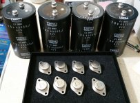
Quick question: Where are you guys sourcing your TO3 insulators outside of the diyAudio Store kit? Does anyone maybe have a Mouser part number for a TO-3 mica insulator?
Dear Rodeodave:
My first stop for components is in most cases Reichelt in Germany.
Look here
:GLIMMER TO 3: Glimmerscheibe für Gehäuse TO 3 bei reichelt elektronik
Worked perfectly for me in restoring my original Sony V-FET amp (TA-4650)
Best regards, Claas
Hi guys,
I have met a problem in my vfet amp building, after successfully tested the resistors when the first time I feed the boards with the PSU voltage. I had 2 resistors R5 and R6 that smoked in both boards. I thought perhaps I burned some transistors... I removed all transistors from the boards
and test them, and for peace of mind I replaced the Mosfets and all the 431(of course the R5 and R6 too)
I used today a variac and start the voltage at 50v, i checked the temperature for both R5 and R6 and they get very hot (I stopped when the temperature reached around 80c), i stopped and I don't know what's the problem!
i join some photos (the vfet are not yet connected! ) i'm using a smallest case is why my
configuration is not standard
Thanks
Attachments
Last edited:
Hi guys,
I have met a problem in my vfet amp building, after successfully tested the resistors when the first time I feed the boards with the PSU voltage. I had 2 resistors R5 and R6 that smoked in both boards. I thought perhaps I burned some transistors... I removed all transistors from the boards
and test them, and for peace of mind I replaced the Mosfets and all the 431(of course the R5 and R6 too)
I used today a variac and start the voltage at 50v, i checked the temperature for both R5 and R6 and they get very hot (I stopped when the temperature reached around 80c), i stopped and I don't know what's the problem!
i join some photos (the vfet are not yet connected! ) i'm using a smallest case is why my
configuration is not standard
Thanks
Looks like TOO much current is going thru those resistors, R5 & R6.
.. see post #1 of this thread, pasted below ...
Mosfet Q5 and Q6 need some voltage applied to their gates in order to turn on (bias) and amplify signal, and this is provided by the voltage appearing across R35 + P3 and R34 +P4. P3 and P4 are there to adjust this voltage so as to set the right amount of current through Q4 and Q6. This right amount of current is defined by 1.5 V DC appearing across resistors R5 and R6 AND the output of the front end (T18) near 0 volts DC. So P3 and P4 not only adjust the idle current through the voltage gain transistors Q5 and Q6, but they also set the DC output that appears on their Drain pins.
Adjusting the Front End bias
Bias is set by measuring the DC voltage across R5, (test nodes T6-T7), and R6 (test nodes T8-T9). Proper bias is when you have 1.5V across each of these resistors, at the same time also having 0 volts DC offset, which is the voltage at T18 to GND.
Adjusting P3 and P4 will make changes in all three of those readings, so in my opinion, you must have three DC voltmeters to make this an easy job. Even the very inexpensive Chinese DMM will work fine for this, just make sure they have good, fresh batteries in them.
A single voltmeter will do that job, but it is more tedious. In any case you want to adjust each pot in small steps, going between the pots and voltage measurements in rotation.
You start with both potentiometers at full counterclockwise, which is the lowest bias setting. At first you are simply looking to get the voltages across R5 and R6 up to 1.5 in small steps. You turn P3 just a little bit, measuring a small change across R5, and then you do the same for P4 and R6. And then you go back to P3/R6 and repeat this process, raising the DC voltages slowly and in equal amounts.
You also want to check the DC voltage from T18 to ground as you do this – you want to keep it near 0V if possible.
I suggest you pause at around 1 V on R5 and R6 – as the Mosfets heat up, the current will rise on its own. Eventually you will find yourself with “warm” settings which give about 1.5V DC bias and close to 0 V DC output at T18.
How good is good enough? 1.3 V to 1.7V is OK for bias. +/-200 mV is good enough for offset at this point. We will tweak these values after the completed amplifier has run for a bit.
REMEMBER – BABY STEPS ON ALL ADJUSTMENTS.
Hi Jaap6, Sorry to be negative but besides what you are talking about. I see two issue with your build. First off, the pots are very hard to access like this these will need a lot of fine tunning (when the amp is hot) and secondly I doubt you'll have enough heatsinking. My sinks are about twice as large as yours and they are already getting up to 49C, you also don't seem to have any ventilation inside the case/holes in the bottom. Regarding your problem. Have you checked the P3/P4 pots aren't all the way down, when you start bringing the front end up.
Last edited:
- Home
- Amplifiers
- Pass Labs
- Sony vFET Illustrated build guide