Hi Dan,
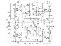
I think you are referring to the DIY SONY VFET R0. Correct?
if so you can change C5 and C6 in the signal path. C1-C4 are RC timing circuits to bring up the bias before the output circuit. Changing them is a problem. I would not recommend it as you could stress your VFETs.
my two cents
I think you are referring to the DIY SONY VFET R0. Correct?
if so you can change C5 and C6 in the signal path. C1-C4 are RC timing circuits to bring up the bias before the output circuit. Changing them is a problem. I would not recommend it as you could stress your VFETs.
my two cents
Attachments
Yes, C5 and C6 are in the signal path- the AC part of that section of the circuit. You will also note that section of the circuit is responsible for the DC biasing of the Vfets. Bypassing these caps with MKP1837 or CDE 940C(as I have in the 2pair version) makes for an improvement in SQ in my opinion.Now I'm getting confused.
Yes, the DIY SONY VFET R0
Are any of the lytic caps in the signal path? (C5 & C6? ), those 2 look like local power decoupling caps to my eyes.
Looks to me as though C1 & C2 need to be >25V, C7 & C8 >30V the other 4 need to be >16V
nash
Thanks @nashbap, Regards C5 & C6, I've some SMT 16V 47uF, and also some 35v 22uF MLCC's that I could use for bypass, although I'll likely swap C5/6 for the Audio Note Kaisei BP 16v 100uF. Same pitch/ size as the Silmics.
I suppose I could simply use the SMT caps in place of all the 47uF Silmics.
I suppose I could simply use the SMT caps in place of all the 47uF Silmics.
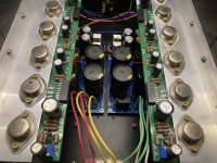
I would admit - yes. This feature was implemented on V2 version of the amp with Teabag boards (see picture). However it is no way connected to the signal path and only used for Vgs delay on start / power-off sequence.I've used Vishay MKP1837 0.1uF as bypass in the past and liked the results.
Would there be any benefit to using them in parallel to a 47uF MLCC nfor C5/6?
Thanks everyone
Attachments
no objections. I used Panasonic FC 3300uf there.Does anyone have any objections to upping the capacitance of C7 & C8? Looks like a good spot for the Panasonic FM 35V, 1500uF cap - Very low ESR
Thanks
Well, they are in the signal path, but not in the manner that you assume. Changing them will affect amplifier stability. In V-FET R0 you can only change C7 and C8. You can see my builds in this thread, I made 4 pcs one for myself and other for friends. Still working good.
Hi again everyone,
I'm just wondering about the voltages across R15 and R16.. I've now got rails of +/-28.6V and I'm getting 3.1 volts across R15.
Build manual says the following :
"If your supply is lower than this, you should adjust R15 and R16 down so that the R19 and R20 have at least 2 volts across them"
Is >3V still okay? My R15/R16 resistors are 44K2 at the moment and if I want to get exactly 2V then I believe I'll need 45k8, if it makes no odds then I'll simply leave as is.
Everything se seems stable / sensible
Many thanks
Dan,
Did you mean you measured 3.1V across R19/R20?
Also, what is your reason for increasing R15/R16 from 41.2K to 44.2K? Are you trying to run the vfets at a higher Vds voltage?
The requirement for min 2V across R19/R20 is to provide an adequate current for the TL431 regulators. A higher voltage (within reason) is fine.
Another question, this time regarding the bias voltage across R32.
After 15hrs of faultless music, I've measured everything again into my 8R dummy loads and reset the bias to 100mV (it was at 70mV up to now. Everything seems completely fine and running just above room temperature.
The amp is built into a Modushop 4U Dissipante case..
Can I/ should I increase the OS bias, and to what?
150mV, 160?
Will this gain me anything, other than a mildly warmer amp?
Thanks again
Last edited:
Nelson says 100mv across the .1 ohm or 1A bias is sufficient.
see https://www.firstwatt.com/pdf/art_diy_sony_vfet.pdf
see https://www.firstwatt.com/pdf/art_diy_sony_vfet.pdf
In my experience with the two pair design, bias changing does effect the tone and speed of the presentation because of the relative H2/H3 balance.
If you can do an FFT, first dial in the bias to get similar profiles between the left and right channels, and then increase as you wish heatsink permitting.
nash
If you can do an FFT, first dial in the bias to get similar profiles between the left and right channels, and then increase as you wish heatsink permitting.
nash
Thanks Nash ")
I have 128 to 130mV now and obviously (subjectivly) more 2nd order & less 'hardness'.
The amp is still running at a very sensible temperature in its 4U case, I've just measured a max of 42degC.
Did I read somewhere that these devices ran at 160mV in the TA-5650? And also in the other DIY Sony amp?
Why 1 amp in this circuit? Sounds better to my ears at 1.3
Thanks again
Last edited:
Overall subjective sound obviously depends on whats before and after the amps. These amps with the Vfets in push pull are H3 dominant. Increasing bias reduces overall distortion and makes H3 even more dominant. It would be instructive to read Mr. Pass' part 2 article on the subject. Here's an excerpt:
"But the big Sony VFET amp project showed that they have something to bring to
the table with push-pull topologies as well. They are surprisingly dynamic
sounding (perhaps due to their mostly third harmonic nature) but like the single-
ended versions, they deliver subtle detail while remaining what I would call
“sweet”, that is to say warm and extended at the top end."
Why 1A? I suspect its where Mr. Pass with his plentiful experience felt it revealed the characteristics of the devices in this configuration, sounded good to him and would appeal to his target audience-us DIYers. He has always encouraged us to twiddle and set bias where we want, recognizing here that the Sony Vfets supplied thru his generosity are quite precious.
nash
- Home
- Amplifiers
- Pass Labs
- Sony VFET Amplifier Part 2