Perhaps you reversed the polarity of one of the two PSU inputs to the amp boards?
This happened to me, reversed polarity. On my amp immediately the TL431 popped with a loud crack and some smoke. So, if you reversed polarity, you may also want to unsolder and check some parts.
Hmm that does not sound good, as I checked the wiring more than once before soldering to the amp boards directly instead of using some connectors 
I hope only the TL431 has gone and not the VFETs, otherwise this amp becomes a dud without the VFETs.
I hope only the TL431 has gone and not the VFETs, otherwise this amp becomes a dud without the VFETs.
An externally hosted image should be here but it was not working when we last tested it.
Last edited:
Some good news I rechecked and found that I have used the positive amp side voltage wiring to the universal PSU board ground
Removed and rewired and now the boards power up correctly but have not checked the playback yet. Will do that tomorrow as its too late here and hopefully it should work as the polarity was not reversed but only the ground cable with positive was mixed up.
Thanks guys much appreciated and found again that working continuously for 4 hrs standing on the amp build makes smoke rather than smooth playback
as the polarity was not reversed but only the ground cable with positive was mixed up.
Yeah, that is what I meant
I think the right term is polarity mixed up, at least from the amp board’s point of view.Right now I am using a single transformer of 0-22V 6.8A*2 (dual secondaries) for the VFET. If I am planning to go with pure dual mono setup as I already have built couple of Universal PSU boards (using currently one), then should I be targetting to have the following voltages and amps?
1. 0-22v 3.4A
2. 0-22v 3.4A + 0-12V 1A
12v is for my UPC1237 based relay speaker protection module as well as to also power my VU meters pcb on the front panel. Or I can drop the 12v and go with a dedicated 12v transformer only for the additional powering capabilities.
I will be using 4 bridge rectifier modules for both the transformers (a pair for each transformer connected to each PSU board for true dual mono setup).
thanks
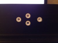
I bought nylon spacers from AliExpress, will check how they fit soon.
They are 5mm length, 7mm outside diameter, 3mm inside diameter for V-FET pins and 4mm inside diameter for bolts.
Now that I think about it maybe I should have bought plastic spacers.
Nylon is not the best material for hot environment.
I received my AliExpress nylon spacers.
5*7*3mm fits perfect and.. 5*7*4mm do not fit.
Actualy it's outside diameter is bigger, about 7.1-7.2mm and T-bracket predrilled V-FET holes are exact 7mm.
Although I want to use M4 mounting bolts for V-FET's those spacers are still good for M3 bolts.
http://www.diyaudio.com/forums/attachment.php?attachmentid=663565&stc=1&d=1519066285
Attachments
You may want to choose exactly the same transformers for 22-0-22 Volt supply, and have a separate 12V transformer. Otherwise your two 22V transformers are not identical model/brand.
Thanks, then my calculation of the voltage and ampere looks fine for 3 individual transformers as below.
1. 0-22v 3.4A
2. 0-22v 3.4A
3. 0-12v 1A
Thanks, then my calculation of the voltage and ampere looks fine for 3 individual transformers as below.
1. 0-22v 3.4A
2. 0-22v 3.4A
3. 0-12v 1A
150VA seems to be a bit undersized for the sony diy vfet amp. i would suggest to go for a not below 300VA transformer.
(unless you mean 150VA for one board which should be fine. but if you have space in your housing go for a higher power rated transformer; the price is not that much more ;-) )
Last edited:
Assuming you are using the Iq of 1.7A to, at rated output, the current will swing to 2x Iq but as Nelson had pointed out before it leaves class A at about 4A IIRC. So I would spec a transformer that handles at least 4A per channel.150VA seems to be a bit undersized for the sony diy vfet amp. i would suggest to go for a not below 300VA transformer.
(unless you mean 150VA for one board which should be fine. but if you have space in your housing go for a higher power rated transformer; the price is not that much more ;-) )
The peak current required to quickly charge up the reservoir capacitors, so your supply ripples are small, I would suggest you need to allocate extra headroom, my rule of thumb is about 50%, or additional 2A min for each 0-22V coils.
In my early years I made similar mistake in calculations, and boy did the transformer get really hot and toasty, the toroidal did survive a few years of abuse before I figured it out but the sound was very strained.
Making
0-22 6A min.
0-22 6A min.
So a 300VA would be much better as others suggested
150VA seems to be a bit undersized for the sony diy vfet amp. i would suggest to go for a not below 300VA transformer.
(unless you mean 150VA for one board which should be fine. but if you have space in your housing go for a higher power rated transformer; the price is not that much more ;-) )
Sorry I meant like 2 independent transformer in a pure dual mono setup. So its going to be 0-22v 3.4A *2 and 0-22v 3.4A *2 (each transformer powering single VFET amp board). But my only worry with high current rated trafo is that the size becomes bigger and I may run out of space to accommodate 2 transformers and 2 universal PSU boards.
My amp is up and running since yesterday night and it looks as well as sounds beautiful. One of the best amps that I have heard so far and currently playing directly from my Soekris DAC and waiting for my BA3 preamp to come from my friend to pair up and see the combination. Then I have the DCG3 to finish
One question regarding the the volume pot either on the BA3 or DCG3 to use for the impedance of the VFET, I think I have the 20k and 10k DACT type pots available which I can use. I also have the Musical Fidelity X10D tube buffer which I might pair with this just before the amp to check if I can get some tube kind flavour
One question regarding the the volume pot either on the BA3 or DCG3 to use for the impedance of the VFET, I think I have the 20k and 10k DACT type pots available which I can use. I also have the Musical Fidelity X10D tube buffer which I might pair with this just before the amp to check if I can get some tube kind flavour
An externally hosted image should be here but it was not working when we last tested it.
An externally hosted image should be here but it was not working when we last tested it.
An externally hosted image should be here but it was not working when we last tested it.
Love it, very nice VU meters!
Thanks Walter but not as great as your builds. Your builds are a great inspiration to me and hopefully with many others especially with the finish and small details that you take care of with the layout, wiring etc.,

- Home
- Amplifiers
- Pass Labs
- Sony VFET Amplifier Part 2