Again without actually seeing it for real... I assumed only one fuse is fitted for UK markets. If it has two fitted and a voltage selector, then "ours" will be the lowest rated fuse (F801 ?) and F802 won't even be in circuit even if it's present.
Yes the bulb is soldered across the fuseholder taking the place of the fuse. I would say first step is to power up without fitting the four switching transistors... lets confirm the first part of the circuit is OK and working.
Yes the bulb is soldered across the fuseholder taking the place of the fuse. I would say first step is to power up without fitting the four switching transistors... lets confirm the first part of the circuit is OK and working.
Fuse - I'll recheck the service manual.
Ok so fit all new parts apart from those four transistors underneath the board then - check!
I'm hoping those C1810s (Q602/604) test fine as well but if not the MJ840s are available on Ebay pretty cheap. I'll test those tomorrow (famous last words - was meant to be this weekend!) when I remove the old components.
Cheers,
John
First steps will be as mentioned, bulb in place of fuse and not fitting the four switching transistors.
Can you work on the PSU with it totally removed from the amp so that all we have is a mains input and nothing connected to the output side to the right of L607 and L608.
On initial powering up the bulb should be dim or even out after an initial surge. If it lights brightly there is a problem.
Things to measure are,
1. Voltages across the two series connected reservoir caps. Should be equal across each. Total voltage should be around 320 ish I would guess depending on the current drawn by the rest of the circuit.
2. Voltage across C613. Can't give a definite value for this but it should be less than around 260 volts dc and should be alterable via the preset.
You did check all the resistors... R601 602 and 603 could have suffered depending how the reg transistors failed.
When you switch off make sure the voltage across C613 has dropped to zero before working on the board again. The voltage across the reservoir caps will discharge via the equalising resistors after a minute or so.
When measuring don't touch any of the PCB or metal work as much of it will be floating at half mains potential.
MJ480 !
MJE340 ?
A lot of dodgy parts on ebay by all accounts.
Firstly thanks for those guidelines Mooly. However I'm not sure - at this stage - if I have the relevant knowledge to carry out all the above without making a mistake of some kind, and I'm not entirely sure what to disconnect from the amp, and what to leave connected 
Working this through, the power from the mains inlet goes straight to a mini PCB board (PSU board 'B' in the manual), then to a larger PCB board (PSU 'A' board) and reservoir caps (C801/805), then to the SMPS, then back out to the large PSU board again ('A' board) and more reservoir caps (C802/C803), and from there to the amp proper... IF I'm reading that diagram correctly & from looking at the amp itself.
I really want to be 110% clear on all this before I start work on it. To be honest I was just going to replaced the necessary parts, then power up straight away and if the fuse didn't blow then set the voltage output to 98-99V and be done with it, but your posts have convinced me otherwise, and to take it slowly & do it right
The 'problem' is the PSU consists of 3 circuit boards really - the SMPS part is designed to be taken out and tested on its side (as per diagram on page 9 of the manual) but it's the disconnecting the relevant parts of the PSU I'm not clear on Mooly - sorry.
Cheers,
- John
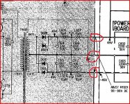
The part to disconnect is as shown here. It's really just the two rails, the plus and minus 49volts that we disconnect.
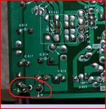
Hard to tell in your photo, but where I have ringed it looks as though the ground track in the middle doesn't connect to a "wire". It looks like a hole in the PCB ? Is that why it mentions a jumper wire I wonder, maybe the ground connection is completed via another route (as in mechanical when it's all screwed together) and when disassembled the ground connection is missing.
No matter, it's just mains into the board we want and those two rails disconnected. Make sure you note any colour coded wires before you unsolder them. With those two rails isolated it doesn't matter whether the ground circuit is completed to the amp or not.
Does that make sense ?
Edit... I think there are three wires... blue to ground ? It's the one on the right I can't see in the piccy
Attachments
Last edited:
Aha that makes sense Mooly - mucho thanks! Yes the earth is via screws and directly to the chassis so there's no wire for that. It's starting to make sense now looking at that excerpt from the diagram - there's life in the old brain yet
And there's just two wires in/out from the SMPS board. I'll get some more pics up later.
Back in bed again alas, but keeping 'em crossed I'll be able to do all that SOMETIME this week. I'm ideally hoping to have it up and running by the weekend.
Ta for the electronics for beginners 'baby steps'
- J
P.S. I'll have to start paying you for your time at this rate haha
Last edited:
Yes you're probably right - that undoubtedly is a tad ambitious all things currently considered. Still the remainder if the parts arrived today, so I am all set. Have read what you wrote about testing the PSU many times over the past couple days, and referenced that with the diagrams and the amp itself and feel 100% confident I know what I'm doing now. An original edition of the 1978 service manual turned up today too and as expected it's much clearer than any of the scans out there. Let me know if you need a better one of the PSU.
Cheers,
- John
Cheers,
- John
Take it slowly checking and testing along the way. Just attempt to get the first stages working correctly.
I'm OK up to now with the manual I have... we'll have to see... if i gets a bit more chewy and all lol.
I'm away for the rest of the day so will be tomorrow when I look in again.
I'm OK up to now with the manual I have... we'll have to see... if i gets a bit more chewy and all lol.
I'm away for the rest of the day so will be tomorrow when I look in again.
Right I've removed all the old caps plus transistors. There's quite a few lifted traces as I thought so I'll have to be a bit careful when it comes to putting those four new switching transistors in place (after I've tested without those in place first). I REALLY dislike working with old circuit boards - the traces lift so easily as the glue has been parched by the heat generated by the SMPS over 30+ years (in this case). Cleaning up old solder-flux residue is also tricky as the isopropyl alcohol can creep under the traces and dissolve the glue, or dry it out. The only other option if the traces did happen to get much worse after the cleanup, is to mount all four switching transistors onto an aluminium bar attached to the underside which should be easy to fashion, and would JUST fit in. I could then just hard wire from the transistor legs to the appropriate points on the PCB. I'll leave that as the very last alternative however
Does anybody have any suggestions for safely removing old heatsink paste from a silpad? The silpad which sits behind the switching transistors must be used again as it is a unique size with various cutouts for certain components to stick through. I don't want to use anything that could potentially dissolve it. I tried hot water and fairy liquid but it had no effect on the gunk at all.
Many thanks,
- John
I'm using an Antex 25W iron and Servisol desoldering braid. I should have added the only traces lifted/lifting are the ones which were obviously worked on before by whomever serviced this amp first. The 'virgin' components have desoldered without a hitch.
I'll give the isopropyl a try on a corner of the silpad and keep 'em crossed!
- John
I'll give the isopropyl a try on a corner of the silpad and keep 'em crossed!
- John
Well the good news is the isopropyl alchohol works well.
The bad, there's a split in the large silpad - bloody typical! It's hair thin and can only be seen if one looks very carefully but I don't want to take any chances with anything shorting out. Here's hoping silpads of this size (approx. 84mm x 45mm) aren't pricey
I'll have to get a very sharp hobby blade too for the cutouts in the silpad - this is going to be fiddly!
Anybody know where to get silpad (or something similar) from which doesn't cost a fortune? I don't to try RS or Farnell as I have no other parts to currently order at present, and I want to get this PSU repaired as soon as.
- John
Last edited:
I'm just testing Q602 (2SC1810 - Sony).
Between the base and collector I get a reading of .558 on the diode testing function on my multimeter.
Between base and emitter I get nothing - it zeroes out.
Between collector and emitter (positive probe on emitter, negative on collector - the reverse shows no reading) I get a reading of .555. As I understand it I shouldn't get a reading here at all?!
On the NPN hFE tester on my multimeter I get a reading of 001 (whatever that means!).
Do I assume from this that this transistor is buggered? It's an NPN and I got the datasheet from here:
2SC1810 Datasheet pdf - SPECIFICATION TRANSISTORS,DIODES - SONY
- John
Last edited:
Today's update: All heatsinks cleaned up - nice job NOT! This stuff's been baked on over the years. All clean and 'as new' again now though.
Just been checking all the resistors: 9 of them are either giving me a wrong reading, or read 0, so I'm going to have to go through one at a time desoldering one leg to get an accurate reading.
Discovered a possible service manual error in going through them. R607 is listed in the service manual parts list (page 46) as 56K (1W metal oxide), and in the 'conductor side' diagram on page 27 as well. However on the actual board is fitted a 100K 1W metal oxide. The circuit diagram in the service manual (page 29) lists it also as 56K here. However a few pictures I've found on the internet show a 100K in place, so not sure what to do here. A bit disconcerting that these errors creep into service manuals though - wonder how many amps have been repaired with incorrect values over the years...!
I'm wondering if an error has crept in between the UK and US/Canadian diagrams perhaps? Not sure how to proceed here, though I guess the amp was running for nearly 30 years on that 100K so perhaps I shouldn't worry!
Q603 and Q604 have been desoldered and test correctly. As I mentioned above Q602 is history, but fortunately I managed to order some NOS 2SC1810s via Ebay (and I also have some On Semi MJE340s if need be).
Have ordered a small piece of 2mm thick aluminum to fashion that transistor clamp. Still trying to find a source for a piece of Sil-Pad cut to size though. Any suggestions?
Step by step, getting there slowly - hoping it'll be worth it all in the end!
Thanks,
- John
Last edited:
Hi John,
Yes any resistors that read suspect must be checked out of circuit. They won't have gone low or short though.
R607 is an interesting one that I spotted looking at the different versions the other day.
For it to be 100K for 220/240 markets and 56K for 110/120 would make sense. And you say 100K is fitted... I'd go along with that. Maybe the discrepency is taking into account the models with a voltage selector... it has to work on both voltages and 100K would not give sufficient current to that part of the circuit. 100K metal oxide sounds original.
Can't just think of anywhere for a large piece of silpad. Individual pads maybe ? Or BUT11AF's they don't need anything for insulation.
Maybe if you measured these and cut horizontally cutting the part with the hole off. Think a TO220 package would sit on that.
MULTICOMP|MK3305|INSULATING KIT, MICA TO-3P/TO | Farnell United Kingdom
MULTICOMP|MK3305|INSULATING KIT, MICA TO-3P/TO | Farnell United Kingdom
Hi Mooly!
Well I've got BUF11As now, and I can't afford to order another set - must use what I have now. I have contacted a company that sell Sil-pad in various sizes but they have yet to reply. If the worst comes to the worst I'll have to get creative with the existing pad - the split is extremely thin and I suppose I could put high temp. insulating tape on the heatsink (the die-cast heatsink / choke/transformer mounting side) just as an added precaution. I'll see...
My TA-F6B does have the voltage selector switch, and is fitted with 100K for R607.
In the manual 100K is for the US/Canadian models only, with 56K for the UK. Perplexing! I think I'll just go with what's already installed as the pics on a couple of other sites (showing the SMPS from the voltage selectable UK/US versions) show the same value fitted (100K). This is the kind of thing that will keep me awake at night though hahaha! (I need to get a life )
Well I've got BUF11As now, and I can't afford to order another set - must use what I have now. I have contacted a company that sell Sil-pad in various sizes but they have yet to reply. If the worst comes to the worst I'll have to get creative with the existing pad - the split is extremely thin and I suppose I could put high temp. insulating tape on the heatsink (the die-cast heatsink / choke/transformer mounting side) just as an added precaution. I'll see...
My TA-F6B does have the voltage selector switch, and is fitted with 100K for R607.
In the manual 100K is for the US/Canadian models only, with 56K for the UK. Perplexing! I think I'll just go with what's already installed as the pics on a couple of other sites (showing the SMPS from the voltage selectable UK/US versions) show the same value fitted (100K). This is the kind of thing that will keep me awake at night though hahaha! (I need to get a life
)Cheers for that link Mooly, but the silpad has to be 84mm x 45mm as it sits between the die-cast structure which holds the large choke & transformer on the topside of the PCB, and the mini-heatsinks for each switching transistor. The whole length of that die-cast piece has to be insulated evidently. I'll try and get a couple pics up to illustrate how it fits together.
- Home
- Amplifiers
- Solid State
- Sony TA-F6B PSU repair