You would need to do a lot more tests. The IC might be unobtainable now which could be a problem.
Check the supplies to the IC
Check the two 0.22 ohm resistors on the output stage. If open circuit then you have an output problem.
Check the voltage across those two zeners near the IC.
Check the supplies to the IC
Check the two 0.22 ohm resistors on the output stage. If open circuit then you have an output problem.
Check the voltage across those two zeners near the IC.
You would need to do a lot more tests. The IC might be unobtainable now which could be a problem.
Check the supplies to the IC
Check the two 0.22 ohm resistors on the output stage. If open circuit then you have an output problem.
Check the voltage across those two zeners near the IC.
I replaced two zeners 22V, but the transistor Q352 and the resistor R 362 are alway very hot, The output stage is 49V, but two transistor output stage are good. Why?
I shall check the supplies to the IC, please show me how to check the IC
Check the 8 and -8 volt rails on pins 4 and 14 of the IC.
Check that there is no DC voltage (<0.1DC) across the base and emitter junctions of Q355 and Q356.
I am going to check Q355 , Q356, and report to you.
I replaced Q 355 ana Q 356 but the transsistorQ352 and resistor 362 are still very hotI am going to check Q355 , Q356, and report to you.
Did you check the voltage across the base and emitter junctions with the amp on as mentioned earlier ?
I didn't suspect those transistors as being faulty. The test was to see if they were turned on")
tbh I think you are going stuggle with with this. Its a complex amp and the IC is an unknown as to whether its good or not. You could always swap the IC with the other channel and see if the fault transfers over.
I didn't suspect those transistors as being faulty. The test was to see if they were turned on
tbh I think you are going stuggle with with this. Its a complex amp and the IC is an unknown as to whether its good or not. You could always swap the IC with the other channel and see if the fault transfers over.
Just a warning for anybody trying to buy some legit 2SB655s. Do not buy from seller 'goodtronic' on Ebay. Actual transistors I received were 'branded' Toshiba and not Hitachi (as pictured/described). The red ink rubs off very easily using just one's thumb! Seller ignored my complaint...
Fake!
HIT 2SB655A TO-3 | eBay
Wish there were some damn-near perfect subs available for the TA-F6B which don't involve any circuit changes :/
John
Fake!
HIT 2SB655A TO-3 | eBay
Wish there were some damn-near perfect subs available for the TA-F6B which don't involve any circuit changes :/
John
Unfortunately this is a common problem with old transistors and eBay - plenty of sellers who, knowing that people are looking for them and are prepared to pay a premium, will just sell fake devices and make a ton. When eBay finally cottons on to them, they just open a new account and carry on.
Modern TO-3 devices are all about power handling rather than anything else. The MJ21193/4 pair is probably about the best there is nowadays. Everything new is flatpacks.
Modern TO-3 devices are all about power handling rather than anything else. The MJ21193/4 pair is probably about the best there is nowadays. Everything new is flatpacks.
Hey,
great thread!
I just had some trouble with my 240V Sony TA-F6b and I wonder, if someone could help.
It was very hot last days in Germany, so first one vu-meter bulb died, than 20min later the other bulb. having some lamps in spare, I changed them, but no light wanted to shine on my meters.
I measured the voltage at the lamp sockets an found without bulbs installed 49V. with just one bulb installed (slightly glowing) 2,8V and with two bulb only 0,7V without glowing. I recapped the PLPS (just the radial elkos) and the elkos C802/803 and C804. I can adjust easily 98,5V with RT601, but i didn't get the meterlights working. Still just 0,7V with both lamps installed.
I measured the resistors R804/805 and R803 (solderd in place) with slight variance to the service manual (5-8%), so i think they should be ok.
does anyone have an idea?
thanks and greetings
hifischrotti
Last edited:
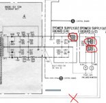
If those resistors are OK then the only possibility is the bulbs (not the correct current draw) or a problem with the soft start relay (which connects across those two lines at the bottom).
If you haven't the correct lamps fitted then the relay won't be getting any voltage and its running via the soft start resistor.
Edit... that's not quite correct in what I say about the relay... I thought it was across the bulbs. My moneys on the wrong bulbs if those resistors are OK.
If you haven't the correct lamps fitted then the relay won't be getting any voltage and its running via the soft start resistor.
Edit... that's not quite correct in what I say about the relay... I thought it was across the bulbs. My moneys on the wrong bulbs if those resistors are OK.
Attachments
Hi,
This is my first post on diyAudio.
I was given a TA-F6B for free, its in near mint condition, and as far as I can tell untouched inside, untill now that is
I'm not realy sure what happend when the amp died, but the output transistors are shorted, at least in one channel, the caps in the PSU are about to blow (all replaced now) and one of the switching transistors is dead (Q611)
Did the output fail at took the PSU whit them (my guess), or did the PSU fail and killed the output, or..?
The fuses and the thermal fuse are OK.
I will check the rest of the transistors and all resistors in the PSU.
I guess all the switching transistors have to be replaced, so I ordered 15 from Dönberg.
The problem is the working original 2023's (all "R" marked) measure about 2 and 4 in hFE, also the 2 in the regulator part (Q601 and 613)
And the new ones from Dönberg measure between 9.5 and 38.
I' using a "Leader LTC-906A" tester.
Collector on Q608 was corroded (missing about a mm) and thereby disconnected, by the glue SONY used on a nearby cap.
I cant figure what disconneting C on Q608 will do the the rest of the PSU, let alone the OP's
Impossible to say the sequence of events for sure, I wouldn't like to hazard a guess on that one. You obviously have multiple issues, perhaps the best approach would be to get the power amps working via a conventional supply first and then concentrate on the PSU. Reasoning being that any amp problems could I suppose damage the PSU. I wouldn't really like to put the PSU protection circuits to the test tbh.
As to the transistors and the hfe etc, well I think having matched identical parts could be a wise thing for the chopper transistors.
As to the transistors and the hfe etc, well I think having matched identical parts could be a wise thing for the chopper transistors.
- Home
- Amplifiers
- Solid State
- Sony TA-F6B PSU repair