That change is negligable...
So back to the beginning and set the pots up again for zero DC offset at the output.
Now something else to try and to measure. First confirm that it's all back as it was and that the offset is zero and that the DC bias current doesn't adjust quite high enough as before.
Measure pin 4 again and confirm its still at around -7 volts.
Now turn down the bias current to minimum and measure pin 4 again. Is it still at -7 or has it increased to nearer -8.8 v ?
Edit... by all means try as per the manual with a load just so you can see what happens")
So back to the beginning and set the pots up again for zero DC offset at the output.
Now something else to try and to measure. First confirm that it's all back as it was and that the offset is zero and that the DC bias current doesn't adjust quite high enough as before.
Measure pin 4 again and confirm its still at around -7 volts.
Now turn down the bias current to minimum and measure pin 4 again. Is it still at -7 or has it increased to nearer -8.8 v ?
Edit... by all means try as per the manual with a load just so you can see what happens
Also just noticed that R306 and R356 have what looks like ever so slightly cracked glaze in the middle of each resistor, and they look very slightly discoloured in the centre too. Ditto to a lesser extent with R307 and R357. Even though they appear to be working OK (i.e. no sudden jumps in measurement) I'll replace those with some 0.6w metal films I have.
OK - with the DC bias trimmer at zero, I am now able to get -9v at pin 4...
Curiouser and curiouser!!!
Indeed !
OK, here's what I am thinking.
I remember telling you earlier that the transistor types won't make a difference... and that's true as regards "volt drops across junctions". That's cast in stone and down to the properties of silicon.
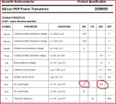
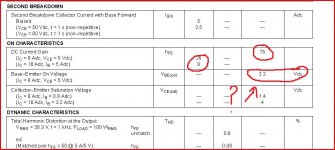
However... I have tried to find info on the output devices and although I can't find much I see they are quoted as having a DC current gain of 35 to 200. Now 200 is exceedingly high for an "old" device and knowing how Sony often select devices...
You see what I am thinking is that if the gain of the ones fitted as replacements is low, and if any others in the stages before have been replaced too, and they also are low gain devices, then in order to get the required 100ma bias in the outputs (to generate that 22mv across the 0.22ohm) it is going to need more current to drive them. That current comes from the IC and its supply is limited current wise by the resistors feeding it from the main rails.
I can't remember whether you said all the other transistors were original or not ? If not, what is actually fitted ?
What you could try now, again for interest, is to bridge across the 4.7k resistors feeding the IC with say 27k. That would bring the value down to around 4K and give a corresponding increase in current available. Then try and adjust the bias again. If you do that set the bias to minimum first before switching on.
I think if you check those resistors out of circuit they will read OK. Discolouration isn't always a sign of a problem believe it or not depending on the resistor material and glaze.
All four output transistors have been replaced from the original Hitachi 2SD675 / 2SB655 to an OnSemi MJ21193 / MJ21194 per channel.
As far as I can see, all other components look original and match up with what's in the service manual.
I'll try adding that 27k resistor then and see what happens - this amp so far had been an exercise in repairing what the previous repairer did it seems
I guess it might be an idea for me to try and get some genuine NOS Hitachi output transistors to make sure it really is working fully to spec. There are some on Ebay but they look far too modern - probably fakes. Still then I'd not know what gain Sony matched these for. Hmmm....!
P.S. What I don't understand is why I can get 8.8v on the positive side, but not the -8.8V... Am I meant to only add the 27k resistors to the 4k7s on the '-' rail, or all 4 of them? Ta
Last edited:
Just try the resistors first, one across each 4.7k so that the - and + supplies are balanced as far as possible.
Normally DC bias is adjustable to destructive levels on most amps... this amp isn't like most amps though because of that IC and the way the bias is regulated and generated.
Normally DC bias is adjustable to destructive levels on most amps... this amp isn't like most amps though because of that IC and the way the bias is regulated and generated.
Well done Mooly - looks like you've done it again
22mV achievable! I still think I may have to change those trimmers though as it's a nice gradual rise in mV until the last 6th or so of the trimmers range (when it's only gotten to around 10-12mV), then it hops up very quickly all of a sudden for the last 6th of a turn. Very difficult to set an exact target voltage then.
So do I need to look into using different output transistors possibly, or is it fine/safe to use the one's in there now (and they do sound good) with this new resistor mod?
Huge thanks again by the way - I definitely owe you a drink or 3 if you're ever in the Basingstoke area
-8.5v on pin 4 now, and 8.7 on pin 14.
Last edited:
I think for now you have to put it back as it was.
Again, I think the trimmers will be OK. Its "normal" for the last part of the rotation to be non linear as it's where the wiper comes off the resistive track and onto the solid conductive end stop.
My thoughts on this... remove the resistors as mentioned. Now the only issue is that the current isn't adjustable high enough... and we seem to have found out why... low gain outputs. That isn't in itself a problem.
Your choices, experiment with alternative outputs but is it worth it ? From a sound quality point I'm sure there won't be any change.
If you try what I said the other day and set the bias to zero you will probably hear distortion if you listen at low level. Increase the bias even a fraction and that distortion audibly goes. Normally even a few milliamps is enough to eliminate it. Certainly the levels you can set it too now are far in excess of what is needed for that.
The benefits of a slightly lower bias is cooler running and less chance of thermal runaway if things got really hot under heavy drive.
The downside is that it may show up on an audio analyser as not being quite optimum, but we are talking degrees 0.001's as opposed to say a 0.002.
Providing the transistors are genuine and fitted properly I would be tempted to leave it.
If you want to try others then we would have to look at what is available...
Is there any reason not to keep those resistors there now though Mooly? They mean that 22mV is now attainable of course, plus -8.5 is now available at pin 4, which more closely matches the +8.7v on pin 14 than the previous -7.2mV.
Of course if there's a downside to using the 27k resistors I'll whip 'em out now
Out of interest I wish I'd measured the bias before I re-capped/trimmer'd the power amp board. I'm assuming it was also around 18mV with those more modern output transistors, as no other mods had been done. It'd been sounding fine too but I just don't like the idea of using 30+ year old caps. When I'd removed the old ones some did show signs on the PCB of leaking slightly so I think I've done the right thing by replacing them all.
Just been having another look at the specs for the outputs. The Base/Emitter volt drop at high base currents is very high for the MJ's. That adds to the reason why they are behaving like this I suspect
Got to go...
See what you think anyway and have a think what you want to do. Its a case what would you fit other than the MJ's
Got to go...
See what you think anyway and have a think what you want to do. Its a case what would you fit other than the MJ's
Attachments
Downside to the 27k's
I'd be happier with the amp with the bias that adjusts smoothly even if its a little low than where it's a super critical setting, perhaps setting it to around 15 mv rather than maxing it out.
No caps will alter the bias range at all
I think you won't be happy unless it's "right" so let me have think what might be suitable replacements. I'm pretty sure now we are on the right track with this... as you say it's all down to incorrect parts being fitted.
haha same-time posting!
Even without those 27ks in there, setting 18mV was still diffucult with those trimmers, so I think whether it's 22mV or 18mV it will be just as 'difficult' so I'll leave those 27ks there then.
I must admit getting something in there that's a better match (i.e. in sympathy with the original design, rather than some new fancy part just for the sake of it) would be nice.
- Home
- Amplifiers
- Solid State
- Sony TA-F6B PSU repair