It's still all looking good... but just use headphones for now.
I suspect the relay just isn't getting enough volts to pull in smartly due to a low supply voltage. Look at the circuit attached.
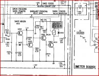
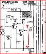
Q407 drives the relay coil via resistor R405. So check the voltage on Q407 collector. It should be zero volts DC after the amp has been on a few seconds. The anode of the diode across the relay coil (D404) is a good place to measure easily usually.
If it is zero, then try smartly tapping the relay with a screwdriver handle (honest) while it's on. It just might twang it across.
If not then you need to temporarily decrease the value of R405 by dabbing another resistor across it, of say 470 ohms.
If the collector voltage of Q407 is not zero and is high then we have a fault.
I suspect the relay just isn't getting enough volts to pull in smartly due to a low supply voltage. Look at the circuit attached.
Q407 drives the relay coil via resistor R405. So check the voltage on Q407 collector. It should be zero volts DC after the amp has been on a few seconds. The anode of the diode across the relay coil (D404) is a good place to measure easily usually.
If it is zero, then try smartly tapping the relay with a screwdriver handle (honest) while it's on. It just might twang it across.
If not then you need to temporarily decrease the value of R405 by dabbing another resistor across it, of say 470 ohms.
If the collector voltage of Q407 is not zero and is high then we have a fault.
Attachments
What is the actual DC supply from that PSU it's running on ?
Can you locate Q407... should be near speaker relay ?
I just know I'm going to get some viscious indigestion after woofing that lot down hahaha!
Right - DC voltage from the PSU measures 38.5V.
The manual specifies 49V so perhaps it isn't enough to get things working fully? No nasties thus far, nothing overheating.
I can see Q407, but unfortunately it is physically impossible to get the multimeter probes anywhere near the legs. I'd have to take the unit apart to do that.
I have got a 35-0-35 transformer in another amp I could desolder and try as a last resort. Having said that I have the remaining parts for the SMPS arriving tomorrow or the day after, so perhaps I should wait until that's tested and running to get the correct voltage into the amp?
Last edited:
"Q407 drives the relay coil via resistor R405. So check the voltage on Q407 collector. It should be zero volts DC after the amp has been on a few seconds. The anode of the diode across the relay coil (D404) is a good place to measure easily usually."
Ah sorry missed this post - yes D404 is just accessible though I'll have to make damn sure the hands don't shake at all!. So the measurement would be from the anode of the diode to the chassis?
Ah sorry missed this post - yes D404 is just accessible though I'll have to make damn sure the hands don't shake at all!. So the measurement would be from the anode of the diode to the chassis?
Don't know what 0L means on your meter. Is it over range ? What voltage range are you on ? Try a high range and measure.
We are looking for zero volts on that point.
Is the resistor R405 hot or at least warm ? It should be.
John... I think I'm going to have to leave it there for today. The fact the outputs are all at zero volts is good... I think it's all working, just the relay not pulling in.
We are looking for zero volts on that point.
Is the resistor R405 hot or at least warm ? It should be.
John... I think I'm going to have to leave it there for today. The fact the outputs are all at zero volts is good... I think it's all working, just the relay not pulling in.
It just means 'no reading' as all the slip of paper says for the meter - not terribly helpful I know :/
Yes have tried on the different settings.
To be honest I'd rather not stick my finger in there it's quite a rats nest of components and lots of exposed components legs...
No worries Mooly and a gazillion thanks for your tireless help again - 'tis much appreciated Sir!
I think I'll wait until the SMPS is ready, and tested and then give it another whirl with it all connected up properly. As you say all the outputs are zero, the power is getting to the VU meters at least, nothings gone bang and no magic smoke! I'll just have to be patient and wait a day or two. All good things and all that")
Cheers and have a good evening!
Yes have tried on the different settings.
To be honest I'd rather not stick my finger in there it's quite a rats nest of components and lots of exposed components legs...
No worries Mooly and a gazillion thanks for your tireless help again - 'tis much appreciated Sir!
I think I'll wait until the SMPS is ready, and tested and then give it another whirl with it all connected up properly. As you say all the outputs are zero, the power is getting to the VU meters at least, nothings gone bang and no magic smoke! I'll just have to be patient and wait a day or two. All good things and all that
Cheers and have a good evening!
FTFY
Looking good! Make sure your 'function' switchs are set to the right input and that the 'tape copy' and 'monitor' switches are set to 'source.' Play with the speaker selector switch, too, since it may be dirty.
Yep all checked and re-checked and switches/controls worked up and down, left and right, round and round etc. Reckon it just needs more than the voltage I was supplying it with to literally come on song.
Hopefully if those three resistors arrive tomorrow I'll be able to get the SMPS up and running, and tested. By the end of the week (perhaps earlier) I'm hoping she'll be singing at last

How's your amp doing?
On DC Volts, "OL" will be "Out of range". A zero reading would be 0.00.
Yep that would make sense! Thanks
Does anyone know the maximum volts that R601,602,603 'see' in the SMPS? I lack the abilty to work this out from the schematic alas, but it looks to my untrained eyes that all three touch a 250V track?
I blindly ordered 3 quarter watt carbon film resistors the other day (same wattage as listed in the service manual) and noticed earlier today on their datasheets their maximum limit is 250V DC.
All 3 values (180R, 68R and 47R) are from the series listed here:
http://cgi.ebay.co.uk/100-X-180-OHM...917?pt=LH_DefaultDomain_3&hash=item230c6034c5
Are they up to the task here or not?
Thanks,
- John
EDIT: Decided to order 2W Kiwames for these resistors to be on the safe side, and also ordered extras to replace the 'blue variety' (still carbon film, according to the manual) types on the SMPS board which had crumbled for those 3 values mentioned above. That type all look very frail compared to the others on the PCB so I'll sleep better knowing those have all been changed. Used Kiwames many times before and they're reliable, high 2W wattage in a small package, 500VDC max and don't cost the earth.
Last edited:
Hi John, I want to see this working now as much as you. We just have to be methodical.
Resistors 601/2/3 see very little voltage. The base emitter junction of a transistor sees no more than 0.7v ish forward biased and it's never run normally reverse biased anyway. Those resistors if you look, are all across B-E junctions and there purpose is to "pull" or "discharge" (that's not the right term but easier to understand) the junction to ensure a quick turn off of the device.
That's essential with any switching PSU. You don't wan't the device to "linger" in a partially conducting state as that increases power dissipation.
So back to the amp. A lot happened in a little time yesterday. I think we need to confirm as best we can that the amp is 100% rather than just connect it all up and hope.
There's no shock hazard as such poking around the power amp as it is running off your external PSU. Obviously just be careful not to short anything with the meter probes as that would be a disaster.
Just to recap we need to be sure that,
1) The four output transistors do have essentially zero volts DC on their cases. That is the most important test really at the moment. If that is zero it means all the DC conditions in the power amps are OK.
(Another test I would like to do before it all gets connected up to the SMPS is to check the quiescent current (bias) of the amp and make sure it adjusts smoothly, and that we set it to minimum before applying the full rail voltage). It's all easy stuff to do.
2a) With your meter on the same range that you measure the main supply rails with check the voltage on anode of D404. What is it ?
2b) Now check the voltage on the cathode of D404. What is it ?
[if you still get this 0L reading then we need to investigate why. I looked up your meter... for these tests keep it on 200 volt DC range. On older equipment the metal parts, chassis etc, can oxidise and you don't always get a good connection with the probe. If that were the case that might explain the 0L reading. Perhaps screw the negative probe to one of the speaker - (minus) terminals which will be a true zero point. That makes it much easier to measure as you only have one probe to bother with.]
Hope your feeling better tomorrow John... although I'll probably be out all day.
Just take it slow...
Thanks.
Perked up a little so managed to test the transistor casings again.
All of them measured zero on the 200v setting on the multimeter. Moving down to the 20V setting they all read approx. 0.014.
D404:
Anode to chassis ground = 38V
Cathode to chassis ground = 38.3V
As you suggested, I found that the leads on many components were quite dirty from years of dust and ambient heat baking it on - I think that's why I didn't get a reading with it yesterday. A good brush with a cotton bud and some alchohol did the trick.
- John
Last edited:
Probably not out all day now... flippin weather !
Voltages on diode show relay isn't being activated, so we need to find out why. Again it could well just be the low supply.
Just been looking at the circuit.
The relay driver/s Q406 and Q407 need four conditions to be met before activating.
1) That the DC offset is zero... and it is.
2) Q312 and Q362 are called "impedance detect" and these monitor current in the outputs. If these turn on then that stops the relay pulling in. I don't think there will be a problem here.
3) Two thermistors TH401 and 402 measure temperature and trip the relay accordingly.
4) A muting delay circuit... probably the low supply here preventing activation.
OK... so we need to just get some sound from the amp easily to prove it's basically OK.
If you connect a jumper wire between chassis (zero volt rail) and D404 anode that should operate the relay (assuming the supply is high enough).
If the relay operates then connect just headphones and listen. If that's OK try a speaker...
Always connect the speaker or phones after the amp has been on a few seconds and disconnect h/phones and speakers before switching amp off to avoid loud thumps and bangs as the all the muting is inactive with the relay permanently energised.
Attachments
Annnddd.......... we have sound through headphones & speakers!!!
You're a genius Mooly, and (yet again!) many many thanks!!!
Sounds fantastic from the little I heard. Only things I'll have to address at some point are sensitivity levels - going through Aux1 I had to have the iPod at a quarter of its full output level and even then the sound was very loud at a low volume setting on the Sony.
Also the left VU meter moves a little sometimes, but seems pretty dead. Perhaps I need to replace the caps for that at some point.
Still those are minor and I am over the moon that the amp is basically in very good working order!
Thanks again to Mooly and all who have helped with this.
Right I guess the next stage is to get that SMPS finished, tested, and installed, then do the bias/DC adjustments as detailed in the manual.
- John
Hi John, that's great news.
Remember to make a note of anything we link or short out along the way as it's easy to forget sometimes just what has been done.
Well, I don't know if you have the bulb in circuit but it sounds as though you can give it a proper workout to test if you want... just remember to connect the speakers after powering the amp on and disconnect before power off.
Stuff like the meter should be easily sorted... as long as the meter itself is OK.
As jaycee says the input sensistivity is probably much higher than todays norm, again easily alterable.
Strange to say neither yours or jaycees posts triggered the thread notifier...
- Home
- Amplifiers
- Solid State
- Sony TA-F6B PSU repair