I need to correct on my previous comments. When I was wiring the output XLRs, I didn't notice that Sony reverses output jack position with regards to audio PCB channels, so effectively I had the channels swapped for balanced output and correct for unbalanced output.")
Now I find it much better sounding than previously. The 1K Vishays are installed in place of 470R Rikens with LM4562. This op amp seems to be better than LM6172 after all, and it produces less differential offset: 1.5mV and 12mV, so I'm not using coupling caps any longer. The only complaint I may still have is that LM4562 stresses sibilances a bit more, but I guess that can be still improved.
David,
Thanks for the tips on resistors, would those Vishays be available from Texas Components?
Peter Daniel said:I need to correct on my previous comments. When I was wiring the output XLRs, I didn't notice that Sony reverses output jack position with regards to audio PCB channels, so effectively I had the channels swapped for balanced output and correct for unbalanced output.
Now I find it much better sounding than previously. The 1K Vishays are installed in place of 470R Rikens with LM4562. This op amp seems to be better than LM6172 after all, and it produces less differential offset: 1.5mV and 12mV, so I'm not using coupling caps any longer. The only complaint I may still have is that LM4562 stresses sibilances a bit more, but I guess that can be still improved.
David,
Thanks for the tips on resistors, would those Vishays be available from Texas Components?
Glad to hear you got it working.
Are you doing any extra bypassing on the I/V LM4562's?
Did you change the 4700pF cap too?
Have you thought about using the diff to single ended IC as a possible buffer? There are two, and its very close to already being a diff input to diff output drive. Just connect the other inputs out reverse order to the connected op amp and the grounded leg of the 4R diff to the output.
It potentaily a place to add pole too.
I'd guess your I/V is sitting about 8V off ground, and the positive swings might be stressed a bit. That's 8mA of there ~25mA of output current. And the signal swings into the xfrmr might be taxing it. Just a thought. Perhaps its okay though.
Also, I think you really will want to add some resistance in series with the outputs of the I/V stage before you drive the xfrmer.
Are you loading the other end of your transformer at all?
The LM4562 wants less than 100pF ideally, and I'd suspect the transformer is more than that.
Might be your sssssssssing problem....
Then again, the (noise) gain of that I/V stage is quite high though, so maybe that's not it. (unless its loaded with say 1000pF!
I did a simulation in LT spice of the current pulse to the output buffer, filters too. If your interested I can send it to you. I don't have it on this computer though, and its using idealized op amp models, since National doesn't have one yet for the LM4562.
It would not be a big stretch to add in the coupling transformer in an idealized fashon, so at least you can get a good measure of things.
One more easy change to try. The current source that sets the reference for the CSX pulse chip. I think IC107 and 207, Q109, 209?.
I think splitting the 510 ohm into, say two, or maybe three 220R's, and adding a cap to ground from the middle node. (hope that makes sense.) It will totally clean up the 7805 supply, and the current will be rock solid, especially at HF where the 7805 isn't that good, and electrolitics might not be either.
at least better than it is.
I believe that you might want to run three 220R's. I think that will decrease your gain out of the I/V slightly, which is already 2x, so it might be good. something like 510/660.
Its great dreaming about this change a bit before doing it.
David is way ahead of way I want to start. The "end" I presume.
Thanks for your links to AA. They were very good reading and get me more excited to do these mods.
I didn't do any extra bypassing on LM4562 yet but I will try some.
The DC offset is indeed slightly above 8V. It is rather high and I will install 760R resistors, which I have from another project.
Didn't do anyting to 4.7n caps, I may remove them completely though.
I don't want to use any additonal buffers, that was the whole idea for using transformers. The S&B passive stage is similar to that: http://www.6moons.com/audioreviews/musicfirst/passive.html
The differential output from I/V op amp connects directly to transformer, which acts as balanced to single ended converter and buffer with gain. I didn't use any series resistors from op amp output, but will also try. I used similar approach when modufying BiDAT and I still enjoy the results.
As it is now, it actually sounds pretty good, although a bit "hard" so adding more liquidity would be in order.
Yes, I would be interested to see simulations results.
Peter Daniel said:I didn't do any extra bypassing on LM4562 yet but I will try some.
The DC offset is indeed slightly above 8V. It is rather high and I will install 760R resistors, which I have from another project.
Didn't do anyting to 4.7n caps, I may remove them completely though.
I don't want to use any additonal buffers, that was the whole idea for using transformers. The S&B passive stage is similar to that: http://www.6moons.com/audioreviews/musicfirst/passive.html
The differential output from I/V op amp connects directly to transformer, which acts as balanced to single ended converter and buffer with gain. I didn't use any series resistors from op amp output, but will also try. I used similar approach when modufying BiDAT and I still enjoy the results.
As it is now, it actually sounds pretty good, although a bit "hard" so adding more liquidity would be in order.
Yes, I would be interested to see simulations results.
Daniel,
email me and I'll send the sim file.
I would not remove the 4700pF with out additional modification.
The gain of the op amp (noise gain I'm talking about) would be something like 10k/20ohms at high frequecies. I doubt it would be good. The op amp will run out of loop gain which I think would be a negative.
The 68,000pF basically shorts the to IV stages virtual grounds, except for the two 10 R's from the virtual grounds. The other two 10 ohms are in series with a current source, so its a high impedance, and has little affect except for the filter action withe 68000pF, which is important.
There are lots of options one could play with that I think in your situation would take the transformer characteristics into account.
The 4700pF limits that gain to Something around 7 at high frequencies. I was thinking you might want to put a cap in there to keep at least the time constant about the same, but the simulation, with it in AC mode, will show you what the affects are so you can decide for yourself.
I didn't look up the transformer link as I'm very busy today, but did happen to order a couple today for work (split primary 600 to 600 ohm Jensens for my Audio Precision AST-2. I did note that they have about 1nF of input capacitance! That's high enough to perhaps cause problems for an op amp like the LM4562 driving it directly, even at a gain of ~7. Thus I'd for sure try to put some resistance in series. 100ohms would almost always be enough, but you said you have good 220R's so I'd even try that. It shouldn't have any affect below 100~200kHz. Of coarse, I'm assuming 1nF of input capacitance in the windings, and your choice of R will depend on the loading.
From what I know about audio transformers, which is only alittle, there are possible advantages in loading them with respect to frequency response. They are typically flatter when loaded I think. I trust you have that data, but don't be afraid to load them at least a bit, say 1k or so. It will likely be a positive.
Good Luck. Look forward to hearing your hearing results!
Portland Mike
p.s. I attatched the ltspice simulation.
Its set up in AC mode. If you go to transient mode, it just puts in a 50% duty cycle 44Mhz pulses. You can observe the waveforms as they go thru the circuit and the affect on aliasing.
AAout is I think the standard analog filter.
AAoutB is with the filters modified for other settings.
There are other possiblities and I only guessed because I don't know the logic.
I believe you are bypassing these though, so its of little concern.
You can also add a transformer. you put down inductors and define a coupling parameter. Look in help or at examples.
I didn't put much time into the op amp models. They are simple single pole models. You can, and I would recommend, that you use a two pole model and add in the open loop output resistance to get a good feel for instability into capacitive loads.
m
Attachments
I must gladly report that the original bridges that Sony used are actually quite good and they do not need to be replaced.
When I was modding ML37 and BiDAT I replaced stock rectifiers with custom made bridges using RGP 15B diodes with very good results. I first noticed those diodes im ML31.5 and they worked there very well, and were actually better than MSR860 I'm using in my NOS DAC.
So I made such custom bridges also for Sony, but unfortunately the results were less spectacular: somehow I got less air and dimentionality. Today, I put back the original parts and again, I started perceiving familiar signature: nice resolution in highs, improved bass, dimentionality and air, that I quite liked in that player after recent mods. So Sony bridges stay. I replaced the other 4 diodes (in analog section) with MUR860 (not parallel as originally) and I didn't notice any major improvement nor degradation.
With regards to output series resistors, I didn't like 244R Vishays S102 there. I placed 33R Rikens in that place though and I think it is better than without any resistors.
Attachments
Diode bridges
Peter,
Prior to converting the CDP to batteries, I installed four custom low-current diode bridges made up by Reference Audio Mods in the USA and noted a major improvement in bass articulation, dynamics and pretty much all other metrics. However, I found little improvement when replacing the stock Sony high-current rectifiers powering the +/-16V supply to the Audio Board. Further improvements were obtained replacing the stock reservoir caps with 4-pole Jensen and the stock filtering caps with inexpensive Rubycon ZA and ZL.
Dave
I tried few times Rubycons, but somehow I was never impressed much by them. I like to use BG N in digital circuits and if those won't be better than Silmics, I will leave the Silmics in place. I am a bit reluctant to touch capacitors yet, as Sony "house signature" is quite acceptable.
And I've listen to audiophile "approved" diodes before, but it was usually pushing the envelope too much for my taste
I am not sure why Sony uses diodes in parallel in audio section. From my experience, things in parallel ususally don't work as good as single.
I will be also disconnecting from PS all the unused sections of output stage soon and this should bring some improvement as well.
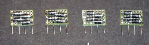
Resistor group buy
I'm putting together a group buy for some high-end Vishay VSMP surface-mount resistors for 16 positions in the signal path on the Audio Board of the SCD-1/777ES. This buy should bring unit price of $18 down into the $6-$9 range. These are very clean resistors with ultralow TCR in the range of .02-2ppm/degree C, as compared to the stock carbon MELF resistors with TCR of 300-500ppm. Email me if interested.
I'm putting together a group buy for some high-end Vishay VSMP surface-mount resistors for 16 positions in the signal path on the Audio Board of the SCD-1/777ES. This buy should bring unit price of $18 down into the $6-$9 range. These are very clean resistors with ultralow TCR in the range of .02-2ppm/degree C, as compared to the stock carbon MELF resistors with TCR of 300-500ppm. Email me if interested.
Re: Resistor group buy
Hi David,
I'm very curious to see what the sonic improvement is with these. I'll pass on this buy though.
Near as I can tell most of those are in series with binary lines, likely to tame trassmision line affects. Maybe the ones driving the current pulse circuit would matter some.... from an engineering point, but more than half the time things that sound good don't make sense from an engineering point.
I do hope they are not any higher inductance than other choices though, as that might matter a bit more than precision.
Best Wishes, and keep us posted.
btw. How do you make you CD player work with the cover off?
Thanks
Portlandmike
David Garretson said:I'm putting together a group buy for some high-end Vishay VSMP surface-mount resistors for 16 positions in the signal path on the Audio Board of the SCD-1/777ES. This buy should bring unit price of $18 down into the $6-$9 range. These are very clean resistors with ultralow TCR in the range of .02-2ppm/degree C, as compared to the stock carbon MELF resistors with TCR of 300-500ppm. Email me if interested.
Hi David,
I'm very curious to see what the sonic improvement is with these. I'll pass on this buy though.
Near as I can tell most of those are in series with binary lines, likely to tame trassmision line affects. Maybe the ones driving the current pulse circuit would matter some.... from an engineering point, but more than half the time things that sound good don't make sense from an engineering point.
I do hope they are not any higher inductance than other choices though, as that might matter a bit more than precision.
Best Wishes, and keep us posted.
btw. How do you make you CD player work with the cover off?
Thanks
Portlandmike
Resistors
Before recently discovering the Vishay SMDs, I had already put radial-lead MK132s in the 16 positions in the signal path on both sides of the S-TACT, and also Caddock flip chips in the path between Current Pulse Converters and I/V. They all made a smart improvement in resolution & transparency that the stock Sony really needs. Putting Vishay SMDs in these positions and around the Timing Chips is an experiment to see if things improve further.
To run with the cover off, use solder to bridge the two PCB land to the left of the connector on the Main Board that accepts the ribbon cable from the cover. The lands are marked with arrows "Loading Assy Short Lands."
Dave
LM4562
To your question about the LM4562, I was thinking about its single op amp derivative for another application and received the following discouraging responses on another forum. If this op amp sounds worse than the AD712 I would stay clear of it in the Sony.
http://www.audioasylum.com/audio/tweaks/messages/143105.html
Re: LM4562
Hi David,
That's interesting. But also there are about 10x more that rate it quite well.
w/o knowing what the circuit is, what gain its running, what cap its driver. No op amp sounds good when it is not running right.
If the guy had a unity gain Sallen and Key filter and was not paying attention to the output cap... there are so many things.
Maybe it does suck and most people reporting great results are just wanting to hear it because of its specs. I'll reserve my decision for my own test. I also do want to try the LM6172 though.
I'm still looking to try it. There is a thread on the LM4562 and there are many positive testimonials.
The AD712 can drive lots more output cap. Its slow in comparision, and has lots of gain and phase margin.
David Garretson said:To your question about the LM4562, I was thinking about its single op amp derivative for another application and received the following discouraging responses on another forum. If this op amp sounds worse than the AD712 I would stay clear of it in the Sony.
http://www.audioasylum.com/audio/tweaks/messages/143105.html
Hi David,
That's interesting. But also there are about 10x more that rate it quite well.
w/o knowing what the circuit is, what gain its running, what cap its driver. No op amp sounds good when it is not running right.
If the guy had a unity gain Sallen and Key filter and was not paying attention to the output cap... there are so many things.
Maybe it does suck and most people reporting great results are just wanting to hear it because of its specs. I'll reserve my decision for my own test. I also do want to try the LM6172 though.
I'm still looking to try it. There is a thread on the LM4562 and there are many positive testimonials.
The AD712 can drive lots more output cap. Its slow in comparision, and has lots of gain and phase margin.
LM4562 loading
Peter Daniels,
I've been informed that there are some favorable improvements in the LM4562 if it is loaded from a current source to the positive rail.
In your I/V stage, the op amp will be positive output, and sourcing current.
You may want to put a stiff CRD to the positive rail, or maybe change the reference current polarity. Not sure if that will work with the current pulse though.
Just thought I'd let you know.
Adding one or two CRD's to the positive rail on the outputs would have the further benifit of unloading the I/V op amps, which couldn't hurt.
Best Regards,
Mike
- Status
- This old topic is closed. If you want to reopen this topic, contact a moderator using the "Report Post" button.
- Home
- Source & Line
- Digital Source
- Sony 777ES laser