ohenry said:At the risk of repeating scores of other posters, I have to brag a bit on my stock TA2024 evaluation board.
Did you use the mini version that you talked about in a previous post?
cjunk said:
Did you use the mini version that you talked about in a previous post?
No I didn't, it was the EB TA2014 board. I decided against using the mini board after talking to Tripath. The mini board is only good for low-moderate power without adding a heatsink and the full-size model needed no additional heat management.
MEXXX said:I've posted about these before, but here they are again.
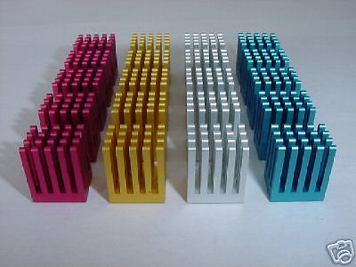
I use them on all my SI's and they fit like they were made for them.
Does the added heatsink get warm during use? The reason I ask is that the underside of this chip has an exposed copper heatsink strip meant to seat on PCB cladding. Too bad it is not on the top. I am curious if there is any real benefit to the added heatsink.
speaker
That little chip can get pretty darn hot. It gets hot enough that you can feel it on the top of the stock plastic case. At $1 a piece those heatsinks do a mighty fine job. And yes, they do get fairly warm. As far as how much the extra cooling benefits the little amp, I have no clue. I'm sure its better to have one on there than not.
MEXXX
MEXXX
I've been using my stock SI with an unregulated supply (9V 2A transformer from a wall wart and an extra diode after the bridge rectifier to make sure the voltage doesn't go above 13V) and 8 ohm speakers (90dB sensitivity). So far, the plastic chip case never gets hot enough to burn my finger. Even after playing at moderately loud listening levels for a few hours I can keep my finger on the case indefinitely. I'm sure it would benefit from a heatsink if you're using 4 ohm speakers or are using a supply rail voltage higher than the typical 12V. If I can get a temp. sensor for my multimeter I'll do some tests and let you all know how hot the case gets when idle and after constant playing for a couple hours. I also have all the parts except for the transformer to make a regualted supply and can set the rail voltage right below the max. voltage of 13.2 and see how much hotter it runs. Unless of course someone else has already done this and would be kind enough to share their info.? ")
MEXXX said:I'm sure its better to have one on there than not.
MEXXX
Probably so.
speaker
My SI is powering a 4 ohm load off a regulated 13.8v supply, so I'm sure that has something to do with why it gets as warm as it does.
I'm not sure why people are so cautious about going over 13.2v, I had one running in my car @ 14v into a 4 ohm load at full power for well over an hour and the thing didn't even flinch.
MEXXX
I'm not sure why people are so cautious about going over 13.2v, I had one running in my car @ 14v into a 4 ohm load at full power for well over an hour and the thing didn't even flinch.
MEXXX
My version, at last!
At long last the parts are assembled, the solder is cool, the photos are ready.
All my tweaks and mods are now in a cool chassis.
Not only does it sound great, it looks cool too.
I'm making a few more. Have a look if like.
My amp, the Mauna Kea
At long last the parts are assembled, the solder is cool, the photos are ready.
All my tweaks and mods are now in a cool chassis.
An externally hosted image should be here but it was not working when we last tested it.
Not only does it sound great, it looks cool too.
I'm making a few more. Have a look if like.
My amp, the Mauna Kea
Panomaniac,
Very cool and original chassis. I love it!
Reminds me of a cyborg-octopus I built once. Because of faulty restraint coding, it went crazy and and tried to do a brain probe on my long-hair chihua-hua. I had to put it down.
I does remind of that cyber-steam school of animation, most notably the work of Hayo Miyazaki, the great Japanese animator who did "Spirited Away," "Laputa: Castle in the Sky," and "Nauscica." Great stuff.
Can't wait to see it hooked up in a system.
Best,
KT
Re: My version, at last!
Pano,
Does Dr. Who know about you building amps in Dalek chassis? Davros might get upset, you know. All you're missing is a flashlight nose, toliet plunger arm, and an eggbeater extermination ray! Edit: Actually, your volume knob DOES look like a small dalek sensor nose!
That is one of the most original chassis I've seen. Very *VERY* cool!
I'd be interested in the case, too!
panomaniac said:At long last the parts are assembled, the solder is cool, the photos are ready.
All my tweaks and mods are now in a cool chassis.
An externally hosted image should be here but it was not working when we last tested it.
Not only does it sound great, it looks cool too.
I'm making a few more. Have a look if like.
My amp, the Mauna Kea
Pano,
Does Dr. Who know about you building amps in Dalek chassis? Davros might get upset, you know. All you're missing is a flashlight nose, toliet plunger arm, and an eggbeater extermination ray! Edit: Actually, your volume knob DOES look like a small dalek sensor nose!
That is one of the most original chassis I've seen. Very *VERY* cool!
I'd be interested in the case, too!
Re: Re: My version, at last!
Hey, it does kinda look like a Dalek! Funny.
Well, at least you liked it. It's been called worse names over on some other forums. Can't please everyone.
(FWIW I 've posted only here and Audio Circles, but there seem to be links to my amp pages from all sorts of forums I'd never heard of.)
motherone said:
Does Dr. Who know about you building amps in Dalek chassis?
Hey, it does kinda look like a Dalek! Funny.
Well, at least you liked it. It's been called worse names over on some other forums.
Can't please everyone.(FWIW I 've posted only here and Audio Circles, but there seem to be links to my amp pages from all sorts of forums I'd never heard of.)
KT said:What IS that metal case, btw? It's very cool.
Is it a found object?
Thanks for the compliment.
I can't give away my chassis secret. ( you might laugh!)
Yep, it's a found object - but the search took weeks. And now I know where to find plenty more.
The chassis contained an electrical device, that's all I can say.
Tea Kettle? Coffee Maker? I sent the pics to some non-audio friends and they thought it was awesome. I'm now wanting to build one like that for my father (but add a few more Dalek touches).
Seriously, I think it's pretty damn cool. Very creative. Much better than the plain ol' aluminum boxes I've been stuffing my gear into.
Don't let those guys get you down. They just don't have great taste in observatories and/or classic Sci-Fi
Seriously, I think it's pretty damn cool. Very creative. Much better than the plain ol' aluminum boxes I've been stuffing my gear into.
Don't let those guys get you down. They just don't have great taste in observatories and/or classic Sci-Fi
panomaniac said:
Thanks for the compliment.
I can't give away my chassis secret. ( you might laugh!)
Yep, it's a found object - but the search took weeks. And now I know where to find plenty more.
The chassis contained an electrical device, that's all I can say.
Well, you didn't give away your secret chassis, but you and motherone gave away lots of useful info reagrding tweaks and I thank both of you for leading me down a good path. I finished modding my evaluation board tonight and it's really very pleasing. I'm a little cautious about praising it at this point since I know time really tells if it's as good as I think it is... and I'm pretty excited about it.
I've changed the PS caps and the inductors and added a SLA battery a few weeks ago and that seemed to make it gain 20 pounds and grow balls. Tonight I replaced the surface mount input caps with 2.2uF Auricaps and it improved the tone by eliminating high frequency harshness and providing wonderfully smooth midrange and more controlled bass. With no burn in time it stopped my wife in her tracks and she actually listened for a few songs (a big statement). The imaging and soundstage is almost distracting, she remarked on the separation of instruments and vocals.
For me, the input caps put it over the top by providing an air of refinement that belies the modest nature of this little PC board. Now I'm looking forward to seeing if the little 41Hz kit can better it.
ohenry said:For me, the input caps put it over the top by providing an air of refinement that belies the modest nature of this little PC board. Now I'm looking forward to seeing if the little 41Hz kit can better it.
You said it! The input cap replacement is the single best thing you can do for this amp. Then replace the on-board power supply cap.
Before the mods the amp is just OK. After, it is amazing.
I'm waiting for my 41Hz boards too. They shouls sound even better than the S.I version.
Glad to hear we could help!
Please let me know how things go with your 41hz boards.. I have some aluminum chassis from jrsun that would be *perfect* for those 41hz amps if I can find a torroid that'll fit.
If they sound as good or better than the SI's, I'll be all over them!
Please let me know how things go with your 41hz boards.. I have some aluminum chassis from jrsun that would be *perfect* for those 41hz amps if I can find a torroid that'll fit.
If they sound as good or better than the SI's, I'll be all over them!
Very cool. Would look right at home in Blade Runner or the news room in Max Headroom. My guess is either a commerical light fixture or maybe a chassis for a nautical device. Compass or ???
BTW, great closeups of the boards for clarification. Those SMDs are really intimidating but Im just about to give it a shot. My concern are the thin traces. They dont deal with too much manipulation very well.
amt
BTW, great closeups of the boards for clarification. Those SMDs are really intimidating but Im just about to give it a shot. My concern are the thin traces. They dont deal with too much manipulation very well.
amt
Finally got my new camera so I took some pics of my "Ultra Compact" SI mod. The case is an elcheapo radio shack plastic case. The plastic was uber easy to drill holes in and I didn't have to insulate any connectors so that was a plus.
I know what your thinking...... "OMG PLASTIC CANT STAND UP AGAINST THE EVIL FORCES OF RF!!!!!!". I think having to shield the SI in a mini fort knox of aluminum and steel is a bit overrated. There is no noticeable interference that I can tell. I even got rid of the low pass filter on the input and still no nasty RF to be found.
Anyways, to make things short..... 20k Alps pot, rat-shack knob, reworked input with 4uf Dayton Poly's, 1500uf supply cap, and mini heat sink. I left the 20k gain SMD in place so I can use my MP3 player and DiscMan which have low output signals. The feet are temp till I can find something better.
Click on the thumbs for bigger picks.
An externally hosted image should be here but it was not working when we last tested it.
An externally hosted image should be here but it was not working when we last tested it.
An externally hosted image should be here but it was not working when we last tested it.
An externally hosted image should be here but it was not working when we last tested it.
An externally hosted image should be here but it was not working when we last tested it.
Looks great! And so small. Good work. Nice to see that heat sink in there.
The caps on top made me laugh, that's the biggest problem with modifying these little guys. The input caps turn out to be bigger than the amp! I like your solution.
Interesting to see that you left the 1/8" jack. Is it run in parallel with the RCAs?
As for RFI, well, you won't be getting any more than in the stock plastic box, will you?
You're using battery power?
- Status
- This old topic is closed. If you want to reopen this topic, contact a moderator using the "Report Post" button.
- Home
- Amplifiers
- Class D
- Sonic Impact improvements. Great!