Guess I can't really listen to the AM. Maybe I'll just stream it over the internet, but that always sounds bad. How much shielding do I need if I'm going to try to listen to AM? Can I just tack up some metal mesh or will I need to go with plates?
I'm going to be bi-amping, and my speakers don't share a common ground.
For IMD, it just seemed high, and that effect probably would be accentuated by the one channel only driving the highs. Should I not worry about this?
Thanks for the answers. Right now, my amps and electronic parts are in transit. Hopefully I'll get them up by next week.
Has anybody read this little article put out by tripath?
http://www.tripath.com/downloads/an11.pdf
It says to reduce RFI, you can put small 10uH inductors in series with the speaker outputs. Has anyone done this? I'm wondering if it would affect the sound. Also, it says to put a 10uH inductor on the power supply rail. That's pretty much cake, and it probably won't affect the sound, but the inductors on the outputs, that's a little scary. I suppose if they're small enough, they don't make any difference at lower frequencies. Just blocks the RF from making it to the outputs, right? Can someone comment? Thanks.
philibuster said:Has anybody read this little article put out by tripath?
http://www.tripath.com/downloads/an11.pdf
It says to reduce RFI, you can put small 10uH inductors in series with the speaker outputs. Has anyone done this? I'm wondering if it would affect the sound. Also, it says to put a 10uH inductor on the power supply rail. That's pretty much cake, and it probably won't affect the sound, but the inductors on the outputs, that's a little scary. I suppose if they're small enough, they don't make any difference at lower frequencies. Just blocks the RF from making it to the outputs, right? Can someone comment? Thanks.
?..the T already has 10uH inductors on the outputs....L3,L4,L5,L6....Not very good I'll grantyou but they're there Replace them with better toroids....much better!
Inductors on the power input....Hmmm
It's a little hard to tell from that paper what exactly they are talking about in terms of the 10uH inductors. As stated in the post above, most Tripath amps already havea 10uH inductor on the output. Do they imply another? Hard to say. It seems to be a general overview of EMI, without thought to specific amp circuit design.
Some good tips there, tho. I have already used the AM radio trick to test for EMI.")
Some good tips there, tho. I have already used the AM radio trick to test for EMI.
It's sad that AM is so good at picking up interference that you can use it as a pretty good test for other equipment. That's some strong noise rejection.Some good tips there, tho. I have already used the AM radio trick to test for EMI.
Since I'm using an SMPS, I think I'll try the 10uH inductor on the power input. Do you think I should put it after the capacitors I'm adding to the line, or before the capacitors? Or, I could put it between the capacitors, such as in a CLC filter, but with a much smaller inductance. Only problem is finding an inductor that will take 5A continuous.
The caps on the output are already implemented in the T-amp, but the 10uH inductor, I think, is in addition to the basic lowpass filter. I haven't seen any of those on a schematic ever. The 10uH inductor probably won't cut down the frequency response very much, as it's so small, but just helps to block the RF, if I know what I'm talking about. What do you think? Have you tried it? Should I be the first?
philibuster said:It's sad that AM is so good at picking up interference
It's not that bad. I meant I use the antenna of the AM radio to sniff out RFI. Works great because the Tripath switching frequencies lie right in the middle of the AM radio range.
As for inductors, you can use something from the JW Miller 2100HT series. I have used them on T-Amp outputs.
There are a bit big, too big to fit well on most boards. But they are rated at 7A. More than enough. You can get them at Digikey.com
The new Super-T amp uses 2 inductors in series, I guess they are 10uH each (I'll measure). That gives a 4th order filter. Sure kills the RF. Just about nothing left. But it does NOT help the sound.
I'd like to see what you come up with in an LC filter for the power, the right filter should work well. Tube amps use them all the time. I stuck a large inductor on one of my SMPS and it didn't like it. But I have not tried any further tests.
If you're using a switching supply I would try using an RC filter instead of an LC filter. A resistance will interact less with the switching supply than an inductor would. The downside is that you will get more voltage drop with a resistor, so you have to choose the value wisely.
Hmm....
I'm actually powering two T-amps with the one 5A SMPS. I can trim the voltage up to 5% over 12V, so it's about 12.6V. What value resistor do you think would work? <.1ohms would drop that down to ~12V at 5A. So that seems all right. But what I wanted the inductor for was to block RF on the line. I have 20000uF, so .1 ohms would give a low pass corner frequency of ~80hz. I can't find the switching frequency of the power supply, but they're usually in the >20khz region, right? So at 20dB/decade, it would be about -50dB at 20khz. This seems pretty clean enough. Now to find a resistor that can take >5A.
Can someone tell me how the inductor could mess with the control of the power supply? Will it be too reactive for the current spikes? Thanks.
0.1ohm sounds like a decent starting value. You don't need to worry about the resistor being able to handle 5A because these amps really don't draw that much current. A 1W 0.1ohm resistor would be just fine for a continuous draw of 2A! A couple of 1ohm 1/4W resistors in parallel would even work fine under normal listening conditions (they might get pretty warm though).
Like you said, the 0.1 ohm resistor with the 20,000uF cap yields an 80Hz cutoff frequency which is certainly low enough to filter out RF. Generally, most SM supplies switch above 100kHz.
Without getting into how switching supplies work, let's just say that they're happier driving a more resistive load.
I've built class-A amps that used as much as 1 ohm on the Pi filter. There was a lot of capacitance after the resistor, tho. (as much as 120,000uF on each rail).
The higher the value of the resistor, the better the filtering, but the more you rely on the caps after the resistor to supply peak current.
The higher the value of the resistor, the better the filtering, but the more you rely on the caps after the resistor to supply peak current.
Just finished the stealth mod on one of my new t-amps. I replaced the little tank cap, and jumpered the power. My board says 2005.09.07, LG-102F REV:A0. There is no solder blob under the chip. Just a bunch of little through-holes in an array, that I think are supposed to be somewhat like a heat sink.
Wow... the input mod really fattens up the bass. I likes. I just used some polypropylene 2.2uF caps that I found at the shop. The kick drum has a lot more kick. I have 60mV offset on one channel of the modded version, and 40mV on the other. Is this bad? Could I have caused some kind of dc offset on the input? I definitely removed R01 and R02. I didn't use the soldering iron to do this, I just pried them off with pliers. Any ideas?
I haven't set up the smps yet. I'm just using a 12V 4A ac adapter that I had for my LCD monitor. But you guys were right. It's nice. With the little power brick, it's a little hissy when I stick my head up near the tweeter. Hopefully the filtering caps I put on my SMPS will help me out a bit with that noise floor. Soon, I'll have these things boxed up and ready to go.
For your class-A amp, I think it wasn't really as big of an issue, because you were running a pretty constant current draw through the resistor, right? But with our little switching amps, the power comes in little spurts with the musical peaks, so I think that using a resistor probably isn't the best. I'm just going to try a big cap reservoir bypassed with a bunch of smaller caps.
What's the best point for power entry? Are the battery leads the best bet?
I have a question on setting up my grounds. I was thinking I'd set up a star ground where I ground the power supply with thick solid wire, ground the power supply filtering caps separately, ground each amp separately, and ground the inputs separately. Should I not ground the inputs to the star ground? My phono preamp is going to be grounded as well, so what can I do to keep ground loops out?
Couple other things: I tried the AM radio. I get like one station. But, the station I listen to streams in AACPlus at 128kbs, so it sounds better than any AM radio would. I guess my tuner's only for FM now.
The chips do heat up a bit. I suppose I'll have to order those heatsinks.
How are you guys mounting the boards in the chassis? The only holes they used are way too big for standoffs. Some nylon standoffs? Thanks for the help.
The chips do heat up a bit. I suppose I'll have to order those heatsinks.
How are you guys mounting the boards in the chassis? The only holes they used are way too big for standoffs. Some nylon standoffs? Thanks for the help.
Good to hear that your T-Amp mods were successful philibuster.
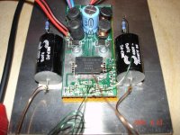
As for mounting the board, I took a piece of perf board about the same size as the T-Amp and sandwiched nylon washers between the perf board and PCB on the 2 existing holes. And added nylon washers on the top side - of course. I drilled and tapped the bottom plate of the enclosure - see pic. Works great!
-Ken
Attachments
Thanks for the mounting tip. I went and got some nylon washers and some standoffs today.
So, I just wanted to see how loud the little tiny board would go, so I drove it to clipping on my 6ohm 86db/W speakers. It's pretty loud at 220 hz. One thing I found out though, is that I probably will need a heatsink. That thing really heats up. Have you guys played with lapping the case? How thick is the case plastic, really? How far down can I go with lapping it? My case is going to be made out of wood, and enclosed, but I have changed the enclosure to a larger one. It's right here. (I think it's going to be "WHISKEY" side out) This will probably help with heat dissipation, but I'll still drill a few holes in the thing for better airflow. I'm going to be mounting the boards on some metal plates that might help with getting the heat out, if I can figure out how to get the heat to the plates.
So, I just wanted to see how loud the little tiny board would go, so I drove it to clipping on my 6ohm 86db/W speakers. It's pretty loud at 220 hz. One thing I found out though, is that I probably will need a heatsink. That thing really heats up. Have you guys played with lapping the case? How thick is the case plastic, really? How far down can I go with lapping it? My case is going to be made out of wood, and enclosed, but I have changed the enclosure to a larger one. It's right here. (I think it's going to be "WHISKEY" side out) This will probably help with heat dissipation, but I'll still drill a few holes in the thing for better airflow. I'm going to be mounting the boards on some metal plates that might help with getting the heat out, if I can figure out how to get the heat to the plates.
philibuster said:How are you guys mounting the boards in the chassis? The only holes they used are way too big for standoffs. Some nylon standoffs? Thanks for the help.
Hi Philibuster,
I drilled two holes in the chassis that correspond to the centers of the mounting holes on the board.
I then used two 1cm or 1.5cm tall nylon standoffs (wide enough to cover the holes) underneath the board. On the top, I used nylon nuts. For the screws, I used two brass screws, though I chose brass just because I had them on hand.
The screws are inserted through the holes drilled in the bottom of the chassis so that the heads of the screws end up on the outside of the chassis. The rest of the screw body goes through the chassis, standoffs, board, and then is secured with the nylon nut on top. The tension of this mounting setup holds the board parallel and suspended over the chassis bottom with no chance of it touching.
You could add a nylon washer between the nylon nut and the board, but I didn't find this necessary because the nylon nut secured right on top of the solder slug, which didn't need protection. I'm not sure how the newer boards with no slug is configured, however.
Best,
KT
Hi Philibuster,
There are a number of things you can do to help cooling. I'm telling you now, after you've mounted the board, sorry.
The easiest is to add a stick-on heat sink on top of the chip. But th best place to draw heat out of the chip is underneath. You can add solder there thru the little holes where Sonic should have put it. The solder will contact the metal slug on the bottom of the chip and give more cooling mass. If you can mount your board upside down, then you could put a stick-on heatsink there. That would do a lot for cooling.
Another slightly tricky mod is to slip a very thin piece of copper under the chip. There is room under most of the chips for thin copper sheet, the kind you get in craft stores. Just keep the strip straight and a little narrower than the chip and you'll have no problems. One in place, you can melt solder thru the holes in the bottom to hold the copper in place. If you make the cooper strip long enough, you could attatch it to your metal case, or a piece of metal, if the case is wood or plastic. That will draw off a lot of heat.
Your chip will thank you for it.
FWIW, I use nylon screws, nuts and spacer to hold the board in place. Works great.
I was thinking about putting some solder in the little holes, but I was a bit worried about it. I might not have a hot enough soldering iron to do so. It's a shame they didn't put the little thermal interface on the frontside. Probably because they thought that just a little solder slug would be enough. I'll try putting some solder in that bad boy. What do you think about thermal paste? I might try the copper strip trick. I think that that probably would be the best idea. Is the metal block on the chip tied to ground or floating?
I haven't mounted the boards in the chassis yet, because I haven't gotten the chassis yet. I'm figuring out the layout of the little guy. Do you think that running the speaker output terminals near the power supply would be a bad thing? It gives me a lot more room to put my boards, while keeping the input leads short. I figure it's better to keep the low level signals away from the power supply than the speaker level signals. Suggestions? Thanks.
I haven't mounted the boards in the chassis yet, because I haven't gotten the chassis yet. I'm figuring out the layout of the little guy. Do you think that running the speaker output terminals near the power supply would be a bad thing? It gives me a lot more room to put my boards, while keeping the input leads short. I figure it's better to keep the low level signals away from the power supply than the speaker level signals. Suggestions? Thanks.
posi-lock
didn't know exactly where to put this so that people may find it....
I'm a new DIY member and am imressed by the cost of high end wire connecting devices. There are some DIYers of sonic impact that have made use of these things...
http://www.posi-lock.com/positwist.html
here is a testimonial from a non music fan of these things...
http://www.webbikeworld.com/Reviewed-motorcycle-products/posi-lock/
If you look closely at the design I think that they may have some real uses in this arena....for mock ups or other places.
Has anyone ever tried these things and tested them with meters and compared them to high end audio connectors?
Thanks for any thoughts.
- Status
- This old topic is closed. If you want to reopen this topic, contact a moderator using the "Report Post" button.
- Home
- Amplifiers
- Class D
- Sonic Impact 5066 Parts List & Modifications