Peter,
Try www.diyzone.net article named Speedo, I think. Thanks to James (tvi) for this information.
Jam
Try www.diyzone.net article named Speedo, I think. Thanks to James (tvi) for this information.
Jam
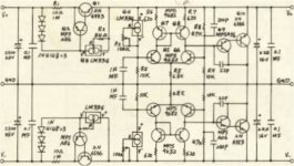
Speedo
It looks kind of stinky to me. Not enough capacitance on output for good stability. Q1, Q2, and Q3 are not even close to a real current source and LM334s blow. You have to know how much load current and shunt bias current you need to design the "Current Source" front end correctly. Just as in lederhosen, one size does not fit all.
It looks kind of stinky to me. Not enough capacitance on output for good stability. Q1, Q2, and Q3 are not even close to a real current source and LM334s blow. You have to know how much load current and shunt bias current you need to design the "Current Source" front end correctly. Just as in lederhosen, one size does not fit all.
Attachments
Power Supply
Why not use some 12v SLA batteries? double them up to +24v / -24v..
use some 10Ah's... last quite awhile.
When not in use.. have a built in charger.
Thats what I have in my amp... +12 / -12v from 2 50Ah SLA batteries.
sounds really good... and no noise or hum.
bypassed at the amp with 220uf Elna Cerafines (50v)
Richard
batteries have their own set of problems. they are a hassle to charge and have high impedance. they are also not as free from noise as you would believe, read some other posts about noise generation under load due to the chemical reactions in the battery.
besides, the initial spec called for AC power only. please be sure to check the requirements list in the general discussion thread before posting.
besides, the initial spec called for AC power only. please be sure to check the requirements list in the general discussion thread before posting.
chokes revisited...
so i had sort of ditched choke filtering/regulation as impractical due to the desire to keep the resonant frequency of the LC filter extremely low, well below 20Hz, which necessitates a huge choke and lots of capacitance. however i was playing with some ideas for a DAC power supply last night and noticed that Hammond makes a 330mH 1A choke. if i paralleled two of these, i would end up with 165mH 2A. used with 20,000uF of filter capacitance, this would give me a resonant frequency around 3Hz... not too shabby. assumming a minimum load of 100mA, we are still above the critical inductance of 53mH as well. thoughts?
so i had sort of ditched choke filtering/regulation as impractical due to the desire to keep the resonant frequency of the LC filter extremely low, well below 20Hz, which necessitates a huge choke and lots of capacitance. however i was playing with some ideas for a DAC power supply last night and noticed that Hammond makes a 330mH 1A choke. if i paralleled two of these, i would end up with 165mH 2A. used with 20,000uF of filter capacitance, this would give me a resonant frequency around 3Hz... not too shabby. assumming a minimum load of 100mA, we are still above the critical inductance of 53mH as well. thoughts?
prototype supply
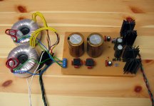
to allow me to prototype a variety of circuits i've constructed a test supply. it is essentially the same as Nelson Pass's BoSoZ supply, a simple pass transistor design. the adjustments i've made are substitution of LM329 6.9V precision references in place of zener diodes, 4 of them in series yielding approx. +/-24V regulated output. i've also substituted a larger 56uF 63V Panasonic FC cap for the reference (MOSFET gate) bypass, bypassed further by a .047uF Panasonic P film. the output of the regulator is bypassed by a Nichicon Muse 470uF cap. i'm using two transformers as suggested in the original design, two 30VCT 50VAC toroids from Digikey, yielding about +/- 50V unregulated output after the filter caps. i have room on my board for four 6800uF 63V Nichicon caps there but i've only installed two for starters.
i'm having trouble viewing residual noise on my 'scope due to some strong interference i'm getting around 9MHz (maybe a problem with my scope or probes?) but i think it is very quiet. the regulation factor is not great, there is a drop of half a volt or so when i connect the JFET buffer circuits, but as long as we are using a Class A circuit it should not be a cause for concern.
Attachments
9MHz
Put a 0.01 to 0.1 cap across each LM 329 for high frequency stability. You may have some parasitic oscillations from the LM329s in series. Do you have a 200 to 500 gate resistor for the Mosfet mounted rigth at gate with very short trace? How about schematic. Nice simple reguator design.
H.H.
Put a 0.01 to 0.1 cap across each LM 329 for high frequency stability. You may have some parasitic oscillations from the LM329s in series. Do you have a 200 to 500 gate resistor for the Mosfet mounted rigth at gate with very short trace? How about schematic. Nice simple reguator design.
H.H.
Attachments
hi harry,
thanks for the suggestions, long time no see")
i'll work on the schematic, but it is essentially the same as BoSoZ page 2:
http://www.passdiy.com/pdf/balzenpre.pdf
the 9MHz may indeed be a parasitic oscillation from the references. in fact, i swear i saw a perfect sine wave on my scope at one point, but i thought i was hallucinating. it is really odd, i will try some film or ceramic bypasses across the references as you suggested.
i have a 221 ohm resistor in series with the MOSFET gates as indicated by Mr. Pass but the trace to the gate is a little long, about 2cm. i will try wiring the resistor directly to it instead.
hey Harry, how does your own Borbely JFET buffer sound? you put a pic of it up on another thread and a few people asked you about it but you must have missed it.
thanks for the suggestions, long time no see
i'll work on the schematic, but it is essentially the same as BoSoZ page 2:
http://www.passdiy.com/pdf/balzenpre.pdf
the 9MHz may indeed be a parasitic oscillation from the references. in fact, i swear i saw a perfect sine wave on my scope at one point, but i thought i was hallucinating. it is really odd, i will try some film or ceramic bypasses across the references as you suggested.
i have a 221 ohm resistor in series with the MOSFET gates as indicated by Mr. Pass but the trace to the gate is a little long, about 2cm. i will try wiring the resistor directly to it instead.
hey Harry, how does your own Borbely JFET buffer sound? you put a pic of it up on another thread and a few people asked you about it but you must have missed it.
Does anyone here remember the old Audio Crafter's Guild Super Symmetric Power Supply? (heh - name borrowed from Pass?)
Anyway, they had a nice little common-mode choke arrangement in there which would block out the identical-but-opposite-polarity rectification noise between the positive and negative halves of the supply... basically just like a CLC pi-filter, but the L component was shared on the same magnetic core by the positive and negative sides so that the noise components would cancel each other out. I thought it was a dandy idea, and it makes good sense... I think I've got a cache of that webpage buried somewhere on my computer. I'll have to dig it up.
Perhaps this would make a good starting point as far as a basic rectifier / passive filter arrangement goes. You could tack on whatever active regulation you like.
BTW - I recall doing a bunch of research into rectifier noise and switching characteristics a while back, and concluding that Schottky barrier diodes were just as good or better than the high speed FREDs and whatnot, at a much lower price. They even had a lower forward voltage drop and needn't be bypassed with little caps for noise supression. The only "problem" with them was a little reverse bias leakage, but of course we don' really care about that in a power supply circuit. The other thing which can help reduce switching noise from the rectifiers is to put series resistors with each diode... you lose some efficiency, but what it does is significantly stretch out and smooth the charging pulses going to the main ripple caps, reducing the peak currents. To take a lesson from tube power supply design, if you use small value caps for the first stage, the peak diode currents will be much lower and there will be fewer high frequency components present. The ripple voltage on those caps will be high, of course, but this can be addressed with subsequent LC, RC, or active stages.
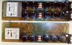
Unfortunately, I have no idea what the resonance frequency was. But this common mode filter choke is not a choke in the conventional sense... I think the series inductance in each side of the filter is fairly low, since the main purpose is common mode cancellation, not series attenuation of non-DC frequencies. If you look at the photo of the power supply, you'll see that the coils are quite small compared to a big power inductor. With some series resistors, I think you'd be left entirely without any resonance frequency. Have a peek at the pictures:
Attachments
Here's a fragment from the original schematic. The "PCB LR"s are zig-zag traces on the PCB which act as inductive-resistive elements at very high frequencies. I can't comment on the effectiveness of this in a power supply, but it seems like it could be a reasonable idea.
Attachments
Note how the currents through the common mode chokes (CMCs) should be perfectly balanced if you've implemented the circuit correctly. Thus, there is no total dc magnetic flux component to saturate the core, and it can be made very small. Actually, upon examining the schematic, I can see that the inductance is actually not too shabby for a choke this size. And, of course the other thing to keep in mind is that the common mode choke effect should counteract any tendancy toward resonance.
Son of etc
Hi hifiZen,
I've seen this before, but have never really understood how this works (really). What is the relative phase of the coils? If there is a current going through the top coil, then the same current is returned through the bottom coil, right? For DC, I mean. So, if they should cancel, we can put a "dot" to indicate relative phase on the left terminal of the top coil and the left terminal of the bottom coil, agreed?
Now for AC, a current through the top coil sets up an induced voltage, same phase, in bottom coil. Does that work against or with the return AC current? You know what I mean? What does it "do" ?
Jan Didden
"...common-mode choke arrangement in there which would block out the identical-but-opposite-polarity rectification noise..." etc. Good grief, where was my brain when I posted all THAT!?! Somebody slap me. I guess that's what you get for posting at 3am.Jan,
you're absolutely correct. The "dots" go at the same end of the choke. Any common-mode voltage appearing at the input of the choke will be blocked from the output side, but differential voltages (like rectificaiton noise and ripple) will not. Thus, the device really does nothing as far as ripple filtering is concerned. It is however useful for filtering out stuff like AC line noise that gets coupled into the supply via the transformer...
Now if only I could cut this foot into smaller pieces... at least it'd be easier to chew before swallowing.
Sorry Jan, didn't mean to confuse you.
- Status
- This old topic is closed. If you want to reopen this topic, contact a moderator using the "Report Post" button.
- Home
- Amplifiers
- Solid State
- Son of Dork: Power Supply