Thanks for the additional pages, but I still can not see the page containing the part list. 
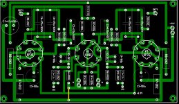
One comment concerning the power supply; now the g2-voltage (450 V) has been created from full supply voltage (1120 V) by resistor R9 (22k 50 W ). There is so some 20 W power dissipated in R9.
Better solution is easily achieved by using both 450 VAC secondaries in series and using only one rectifying bridge.
The principle idea can be seen as a part of the circuit below:
Here the center tap has the half of the full voltage. By supplying the g2-voltage from this point you will save a big amount of power and heat.
In your case the center tap will be at the connection of both 450 VAC secondaries. Of course you need to modify the filtering circuitry a little (electrolytic capacitors ).
One comment concerning the power supply; now the g2-voltage (450 V) has been created from full supply voltage (1120 V) by resistor R9 (22k 50 W ). There is so some 20 W power dissipated in R9.
Better solution is easily achieved by using both 450 VAC secondaries in series and using only one rectifying bridge.
The principle idea can be seen as a part of the circuit below:
An externally hosted image should be here but it was not working when we last tested it.
Here the center tap has the half of the full voltage. By supplying the g2-voltage from this point you will save a big amount of power and heat.
In your case the center tap will be at the connection of both 450 VAC secondaries. Of course you need to modify the filtering circuitry a little (electrolytic capacitors ).
Thanks for the info artosalo.
KK84 said "In my construction I`ve used 3k primary resistance transformer with UL tap on 20% from B+. Circuit run`s nice in pentode mode (Va = 1kV, Ia = 125mA, Us2 = 400V, Us1 = -48V, I reached an 42W on output still operating in A1 class. Connecting G2 to UL tap of tr. power drops down to 35W but sound quality .... huh .... Of course in triode mode internal resistance of tube drops drasticly, so I sugest to use 5k primary res. tr."
I think i will use this tube in pentode mod and UL.
I have also four GM70 to made a DHT SE amp.
Hi
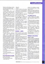
I have now the all article
Enjoy
Happy new year!
I have now the all article
Enjoy
Happy new year!
Attachments

Hi
I have now the all article
Enjoy
Happy new year!
WOW!! That's the best thing I wish having, to starts a New Year.
The only doubt will most likely be how it'll performs with GM70.
I've bought a pair Electra-Print of spec: 7K/25W/120mA/8ohms to spear head this project.
Wishing All a fabulous New Year!
Zekk
Hi Gabrielbecheanu,
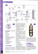
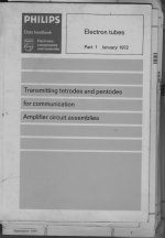
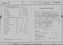
Think that SE Amp design with 813 power tube overlooked max Wg2 disipation and max Ug2 voltage.Same is for Uf voltage(10V/5A) since this tubes is with direct heated Thoriated Tungsten kathode, Uf have to be held to +- 1% of specified nominal value(10V) for best tube performance and longest tube life.
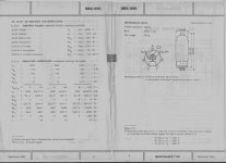
Here is some original Philips dokuments related for tube QB2/250(813,GU13)
I have some expiriences with this tube type(RF),found that GU13 Russian 813 version is the far the Best one.
Salut din Banat si numai bine doresk
Think that SE Amp design with 813 power tube overlooked max Wg2 disipation and max Ug2 voltage.Same is for Uf voltage(10V/5A) since this tubes is with direct heated Thoriated Tungsten kathode, Uf have to be held to +- 1% of specified nominal value(10V) for best tube performance and longest tube life.
Here is some original Philips dokuments related for tube QB2/250(813,GU13)
I have some expiriences with this tube type(RF),found that GU13 Russian 813 version is the far the Best one.
Salut din Banat si numai bine doresk
Attachments
Last edited:
- Status
- This old topic is closed. If you want to reopen this topic, contact a moderator using the "Report Post" button.
- Home
- Amplifiers
- Tubes / Valves
- Someone help: SE shematic with GK71?