Last One: UCC3806 Controller board
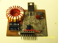
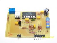
This I did for a modular DC-DC PWM Current-mode SMPS. I wanted to try different controllers, like the UC1846/2846/3846, UCC3806 (BiCMOS version of the '1846), UC3856 (high-speed version of the '1846), and MC33025/34025, without having to re-do the entire board. 90-degree headers made things really easy. Note the optoisolated input for taking feedback from across the Galvanic barrier (transformer).
Gotta love those 1% RN-55D's
Attachments
Re: 6th One: LM2677
Mistake: This was the 5V 5A buck...........
Man! That Pic Resizer works beautifully!
N-Channel said:92+% High-efficiency 24V to 13.5V, 5A - 260kHz Buck, synchronizable, with shutdown. Highest efficiency I measured with this one was just over 93% at full load.
Mistake: This was the 5V 5A buck...........
Man! That Pic Resizer works beautifully!
Not too hard, especially since they're using smt components, I don;t have any hole drilling to do. I do the traces and close-in parts using dry rub-on transfers, and masking tape for the wide-open spaces to make the ground plane. So, what's actually being etched are the separations between all the nodes. Like I said before, two advasntages here: 1) less copper is eaten, so less FeCl3 is used, and 2) takes much shorter time to etch because of #1.
When I worked at National, I designed some of the simple switchers...some of the LM26xx series...
If you have specific questions i can try to help out...
Basically, you first choose your L based on the max current ripple you can tolerate...figure 30% max...
Then the L is choosen for the voltage ripple...
When you are dealing with higher switching frequencies the ESR of the C becomes dominant , so you use ceramics for the low ESR..
Some are voltage mode switchers....then you need to watch where you place your LC double pole...
cerrem
Hi Cerrem,
That's very cool! I don't have any specific questions at this ti..., uh, wait a minute, I do have a specific question! In fact, I have several questions: I seem to remember an App note on how to get more power out of the LM2577, whereby a slave '2577 was synched to a master '2577 by tying the two chips' compsenation pins together and grounding the slave's feedback pin in an attempt to run it "wide open", thus forcing synchronization and equal current sharing. My question is this: Can the same thing be done for the LM2587?
Next question: Can the same technique be done with any SimpleSwitcher lacking a "sync" pin but having a compensation pin? Can this also be done with a buck chip also lacking a sync pin but having a compensation pin?
I'm thinking along the lines of paralleling several SimpleSwitchers for a rather high-current buck, say, from 12V to 5V or even 12V to 3.3V. This would be a great start on doing DC-DC ATX box for a desktop PC, or a DC-DC ITX box for a Book PC. Thoughts?
Steve
That's very cool!
I don't have any specific questions at this ti..., uh, wait a minute, I do have a specific question! In fact, I have several questions: I seem to remember an App note on how to get more power out of the LM2577, whereby a slave '2577 was synched to a master '2577 by tying the two chips' compsenation pins together and grounding the slave's feedback pin in an attempt to run it "wide open", thus forcing synchronization and equal current sharing. My question is this: Can the same thing be done for the LM2587?Next question: Can the same technique be done with any SimpleSwitcher lacking a "sync" pin but having a compensation pin? Can this also be done with a buck chip also lacking a sync pin but having a compensation pin?
I'm thinking along the lines of paralleling several SimpleSwitchers for a rather high-current buck, say, from 12V to 5V or even 12V to 3.3V. This would be a great start on doing DC-DC ATX box for a desktop PC, or a DC-DC ITX box for a Book PC. Thoughts?
Steve
- Status
- This old topic is closed. If you want to reopen this topic, contact a moderator using the "Report Post" button.
- Home
- Amplifiers
- Power Supplies
- some questions about switcher regulator (LM267x family) from National