Some interesting measurements concerning bias levels -
Here are some quick and dirty measurements I did looking at various levels of bias on the F4. ( +/- 22.5V rails )
The conditions are, amplifier to normal temperature, one channel driven (because I cant read 2 at once), input to amplifier 3V 1.1kHz sinewave from 339A, distortion read across 4ohm 100W dummyload resistor, oscilloscope and FFT connected to HP 339A monitor, which was outputting the residual distortion waveform.
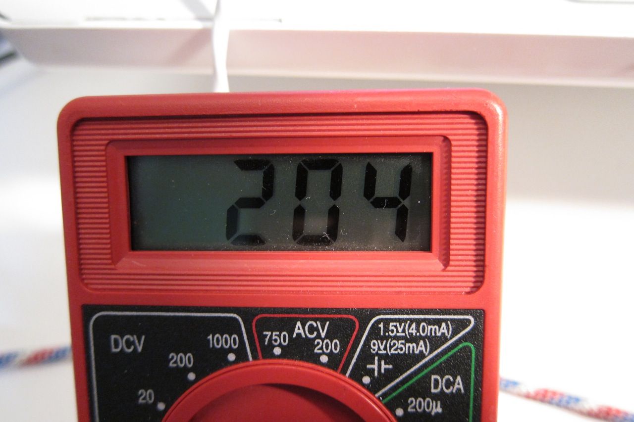
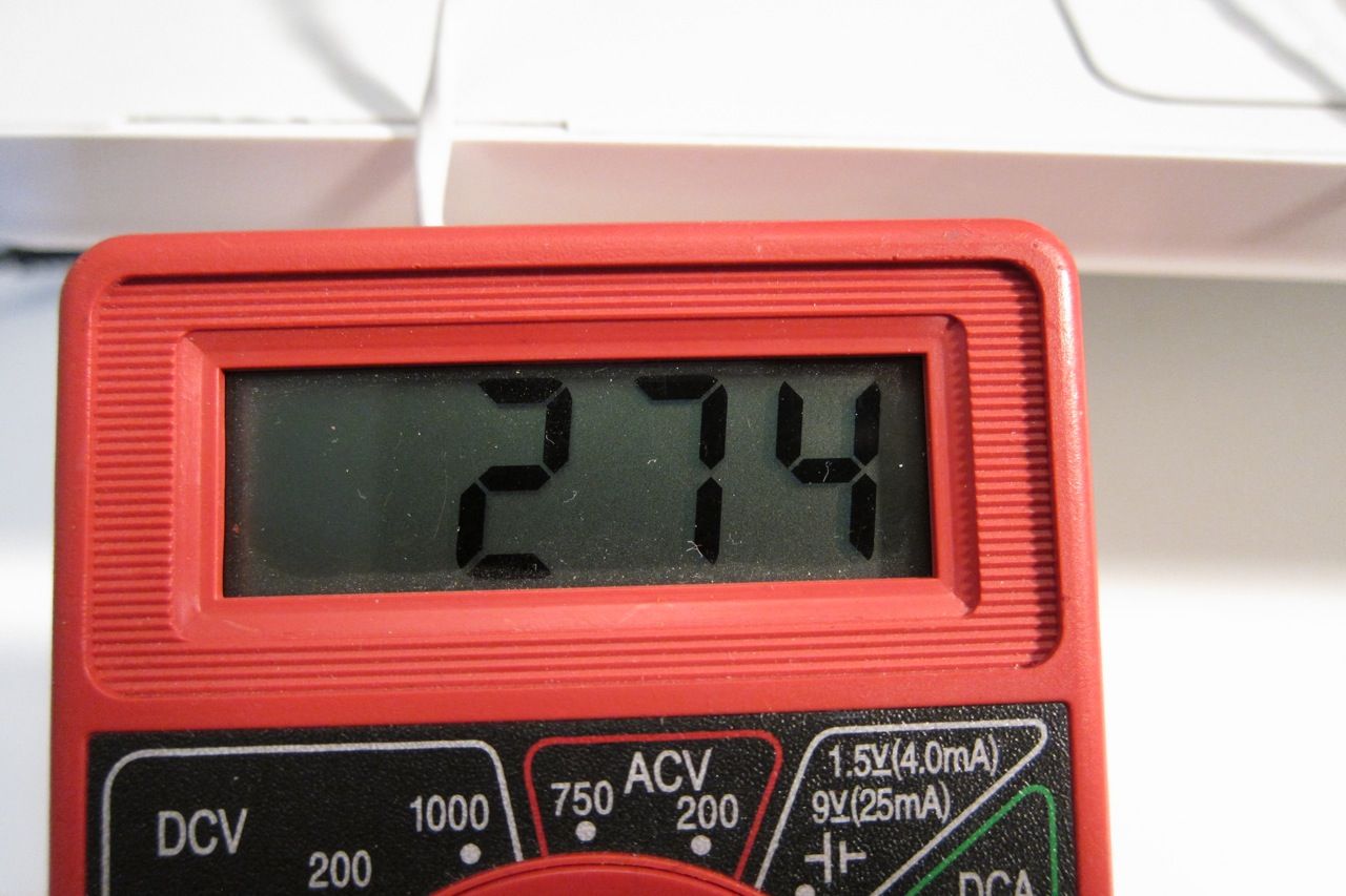
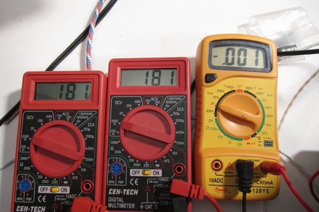
Bias value is mV across .47ohm
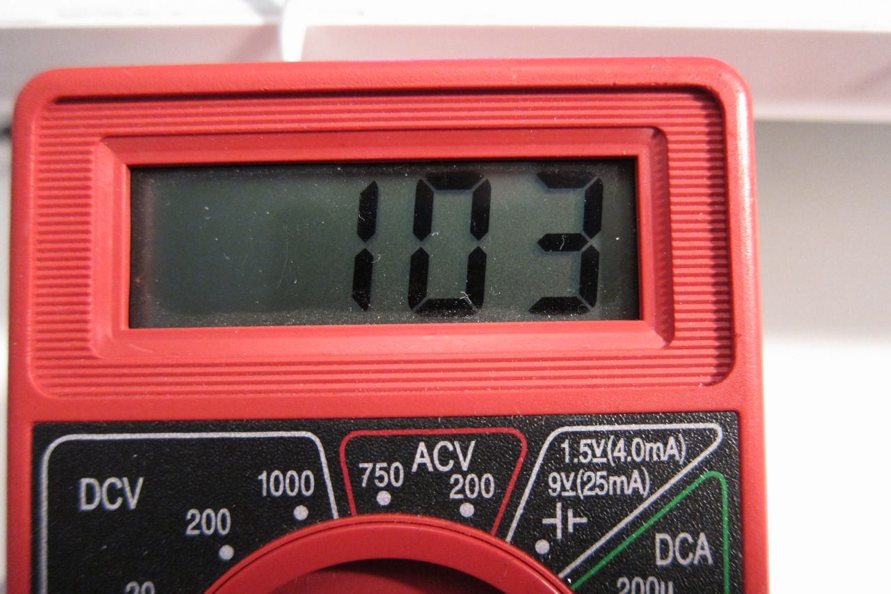
Bias measured across a .47 source resistor. (This is 1/2 the normal level, for illustration's sake)
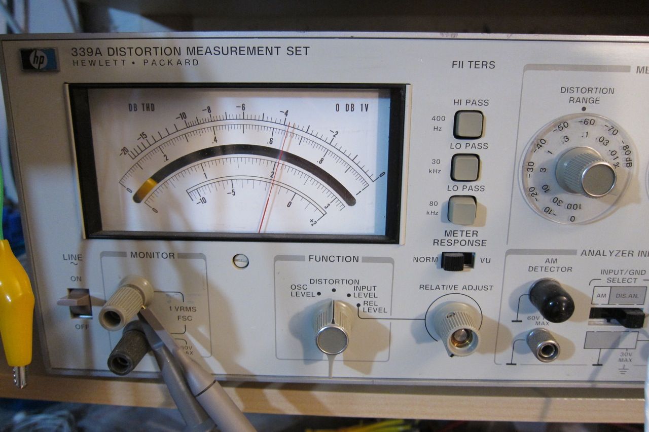
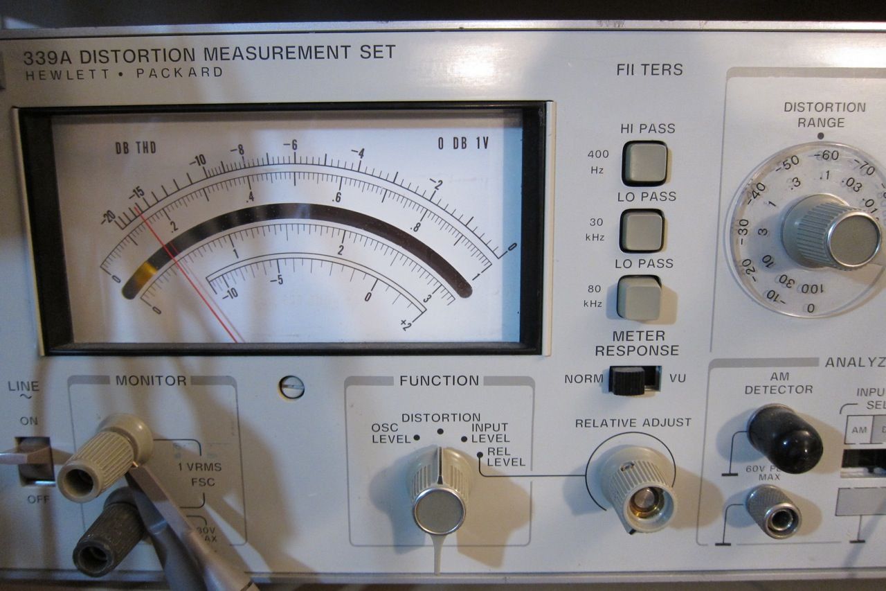
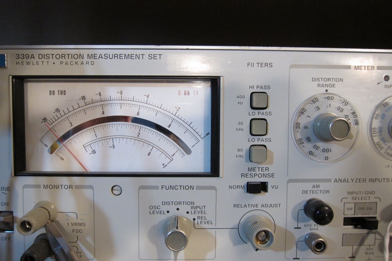
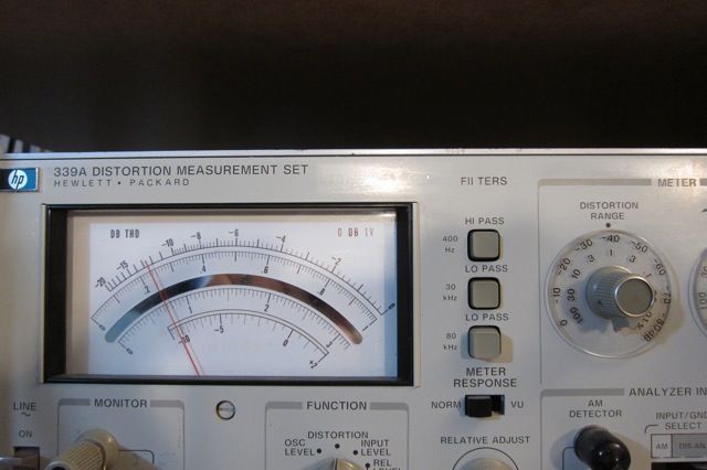
Distortion (Meter is set to the .1 scale, look at the arc above the mirror, here showing .065%)
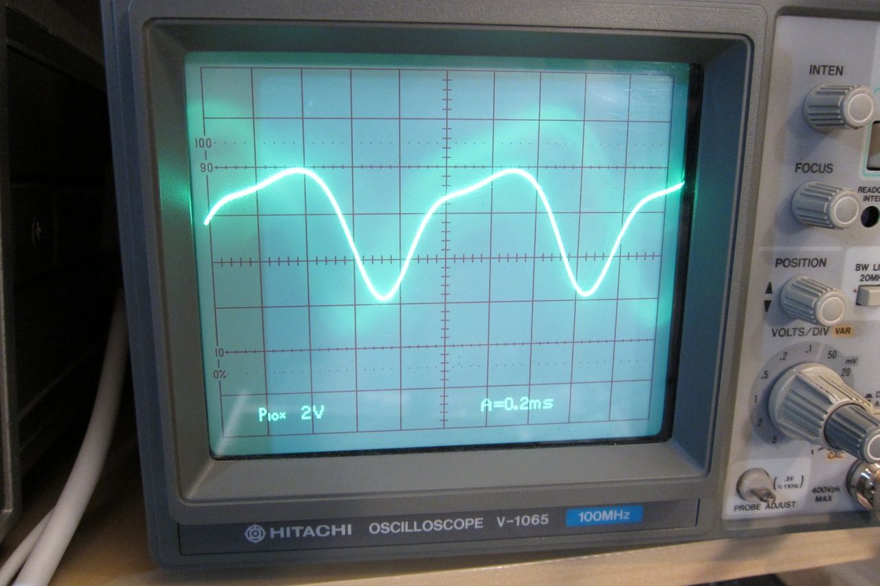
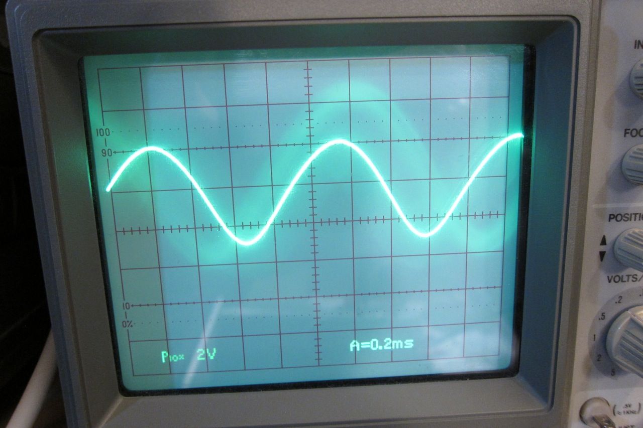
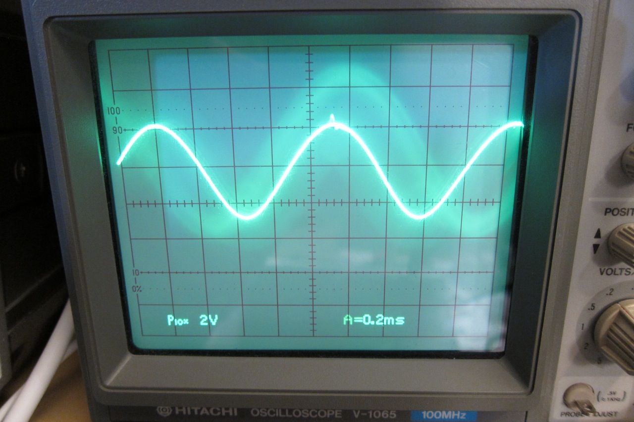
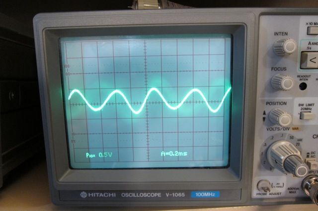
Here is the shape of the distortion residual. (No distortion would look like a perfect sinewave.)
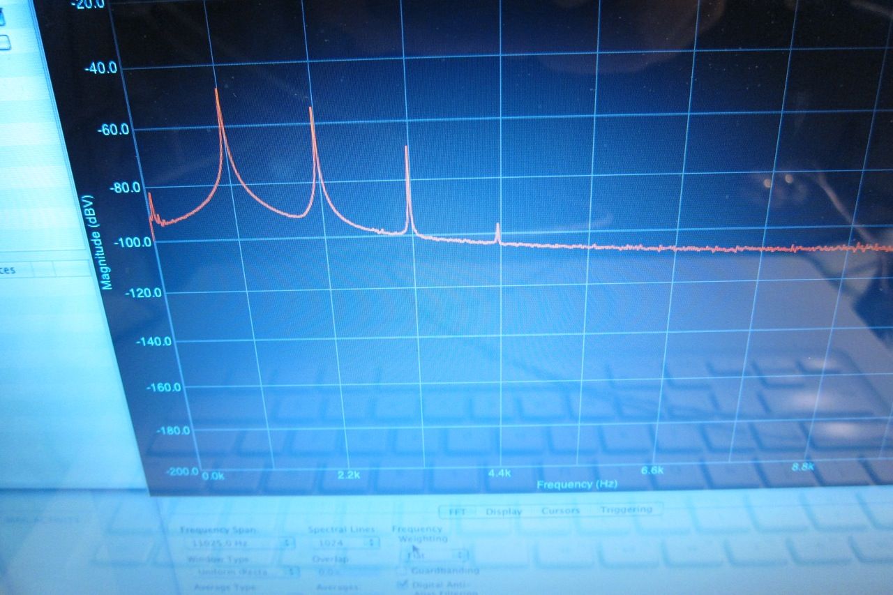
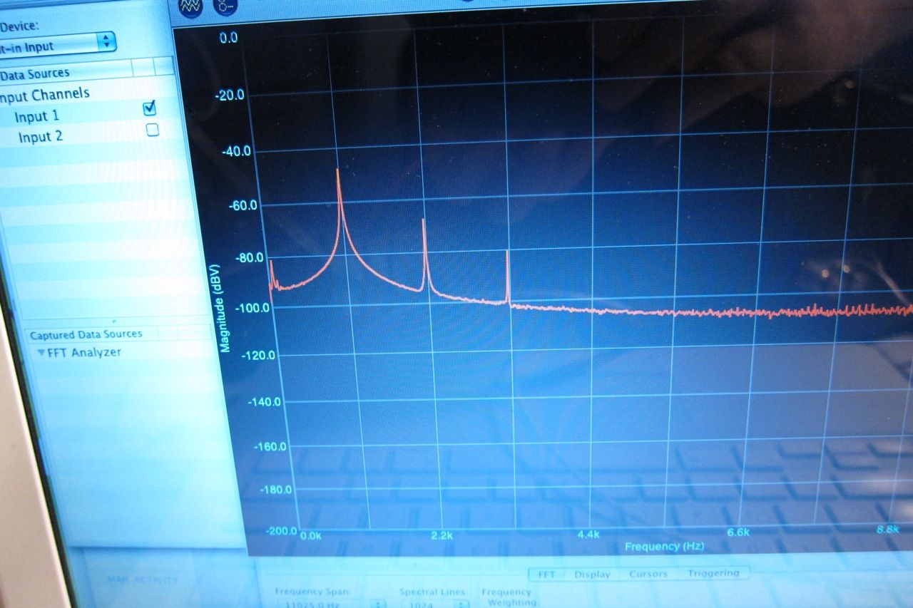
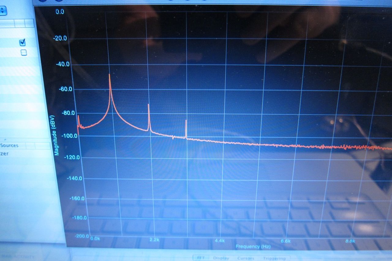
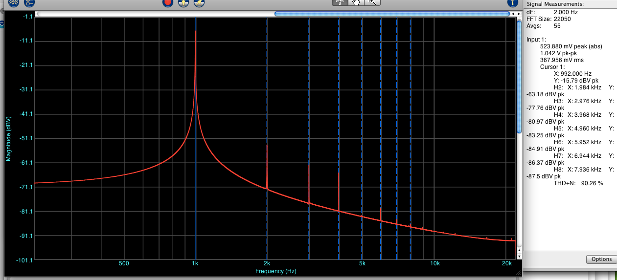
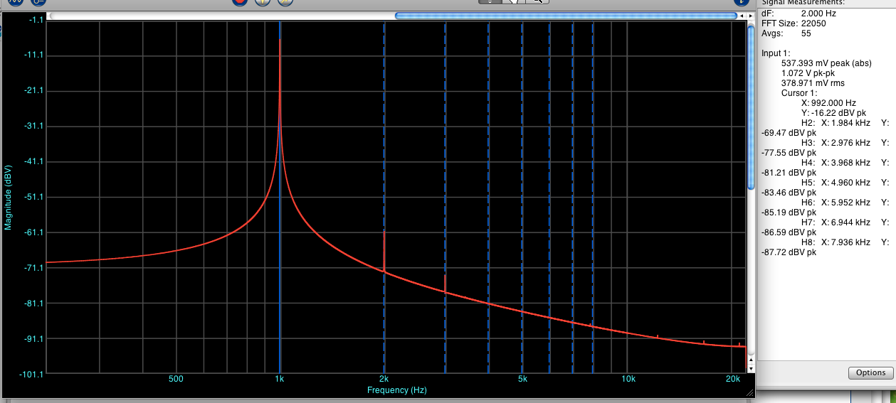
FFT of the distortion residual. (please excuse the photo of the screen. The next time I do this I will get screenshots.) The 1st peak at 1.1k is the fundamental. (1.1k chosen as it aligns with the gridlines. ) Looking right, the 2nd peak is the 2nd harmonic, the 3rd peak the 3rd harmonic, and the 4th peak the 4th harmonic. Higher level harmonics are not visible, as they are very small and lost in the noise.
Now let's increase the bias to the recommended amount, 200mv measured across the source resistors.
Distortion has now decreased to .016%. All that has changed is the bias. What a marked difference!
The distortion residual has lost it's humps and is looking very smooth.
The 4th harmonic is no longer visible, and the 2nd and 3rd are greatly reduced.
Increasing further -
Distortion now .08%
Residual very similar to above, but even more smooth. (A little bit, anyway…)
The noch on the one peak is just a probe artifact.
FFT showing the 2nd and 3rd harmonic even lower. Neat!
So the logical thing is to just crank it all the way up, right? Well, yes and no. Here are the reasons the way I understand it. (and people with more experience please correct me if I'm wrong.)
1) Heatsink - at some point you are going to get too hot. With the 5U that wasn't an issue. A good rule of thumb is the transistors 65C max and heatsinks 55C max.
2) Bias current vs. VA of transformer. You don't want your total bias current (in watts) to be more than 1/2 or maybe 2/3 or your transformer's VA rating.
3) Transistor dissipation. Make sure you look at the datasheet for the output transistors, they all have an absolute maximum and a de-rating as they get hotter. For long life don't set more than 1/2 the max dissipation.
4) Point of diminishing returns. In this example the measured distortion continued to decrease (down to .045 or so) as bias was increased to 370mV, but the gains were very small and it would added lots of heat. The sweet spot was closer to 300mV bias.
Here are some quick and dirty measurements I did looking at various levels of bias on the F4. ( +/- 22.5V rails )
The conditions are, amplifier to normal temperature, one channel driven (because I cant read 2 at once), input to amplifier 3V 1.1kHz sinewave from 339A, distortion read across 4ohm 100W dummyload resistor, oscilloscope and FFT connected to HP 339A monitor, which was outputting the residual distortion waveform.
Bias value is mV across .47ohm
Bias measured across a .47 source resistor. (This is 1/2 the normal level, for illustration's sake)
Distortion (Meter is set to the .1 scale, look at the arc above the mirror, here showing .065%)
Here is the shape of the distortion residual. (No distortion would look like a perfect sinewave.)
FFT of the distortion residual. (please excuse the photo of the screen. The next time I do this I will get screenshots.) The 1st peak at 1.1k is the fundamental. (1.1k chosen as it aligns with the gridlines. ) Looking right, the 2nd peak is the 2nd harmonic, the 3rd peak the 3rd harmonic, and the 4th peak the 4th harmonic. Higher level harmonics are not visible, as they are very small and lost in the noise.
Now let's increase the bias to the recommended amount, 200mv measured across the source resistors.
Distortion has now decreased to .016%. All that has changed is the bias. What a marked difference!
The distortion residual has lost it's humps and is looking very smooth.
The 4th harmonic is no longer visible, and the 2nd and 3rd are greatly reduced.
Increasing further -
Distortion now .08%
Residual very similar to above, but even more smooth. (A little bit, anyway…)
The noch on the one peak is just a probe artifact.
FFT showing the 2nd and 3rd harmonic even lower. Neat!
So the logical thing is to just crank it all the way up, right? Well, yes and no. Here are the reasons the way I understand it. (and people with more experience please correct me if I'm wrong.)
1) Heatsink - at some point you are going to get too hot. With the 5U that wasn't an issue. A good rule of thumb is the transistors 65C max and heatsinks 55C max.
2) Bias current vs. VA of transformer. You don't want your total bias current (in watts) to be more than 1/2 or maybe 2/3 or your transformer's VA rating.
3) Transistor dissipation. Make sure you look at the datasheet for the output transistors, they all have an absolute maximum and a de-rating as they get hotter. For long life don't set more than 1/2 the max dissipation.
4) Point of diminishing returns. In this example the measured distortion continued to decrease (down to .045 or so) as bias was increased to 370mV, but the gains were very small and it would added lots of heat. The sweet spot was closer to 300mV bias.
Last edited:
As you say, diminishing returns. In reality in takes time, listening, and measuring, to decide. My new naked f4 output will have 12 pairs on output. How many I use will depend on the aforementioned investigation. Consider Pass amps and number of pairs vs bias current and figure what each pair is biased at. I think .5A will be my max on big amp. In FW type implementations, where you are trying to yield maximum potential from single output pairs, high bias is ideal, but when more power is needed, things change a hit for a number of reasons.
After looking at this it seems (to my very inexperienced eye) that you would actually want the minimum amount of devices, and therefore the highest bias for your heatsink.
Talking to one of the Gurus sorta confirmed this, but he said to always look for what Nelson has described as the 'Sweet Spot'. In the case of this particular amp, that point is about 300mV, or about .6A per device. Anything past that required a bunch more bias for very little decrease in distortion.
Talking to one of the Gurus sorta confirmed this, but he said to always look for what Nelson has described as the 'Sweet Spot'. In the case of this particular amp, that point is about 300mV, or about .6A per device. Anything past that required a bunch more bias for very little decrease in distortion.
Last edited:
Don't think that is in conflict with my statement. With smaller power needs, I agree. If looking for higher power, I think things change a bit. More devices give more current capability, more thermal capability, more DF, more gain. Consider your bias level of .6A. If you want 200W, you can either increase bias or add more fets at this same bias level. The answer is not necessarily a given. It depends in sinks, load, longevity. I am not saying I am right, just discussing.
Great stuff! Smaller photos would be nice. I think it's very design dependent. Some designs will actually increase their distortion beyond a certain bias. A really good example is a quasi-comp circuit with no Baxandall diode. It just gets hot, it doesn't get better.
There's also thermal stability to consider- high bias can put you closer to thermal runaway. I like to run high power and get things heated up to the maximum I dare, then monitor the bias and see if it's increased and if the system cools down as expected. With good thermal feedback and the right Vbe multiplier you can go very high on bias, if needed.
I've seen some amps where making the decision about diminishing returns is difficult because things really do improve, but at the cost of ever increasing dissipation. I just worked on an old ARC amp and they've got the thing dissipating 200 watts at idle. Dang, not class A, but it shows what happens when you get carried away.
I am not saying I am right, just discussing.
Nor was I trying to correct you!
")
The point of this post was merely to get the discussion flowing, and it's doing exactly that.
I want to try a Burning Amp complementary output with 2 pair and 4 or 6 pair, with similar total bias and see what the subjective difference is. It would be an interesting project.
Great thread. Thanks for posting this. I'd love to see what you find in a similar analysis of your F5 turbo.
I will do the Standard F5 next, and the Turbo as well.
Pass DIY Addict
Joined 2000
Paid Member
6L6,
any chance you could attach your pics?
any chance you could attach your pics?
if your transformer is feeding a capacitor input filter then that recommendation will cause a lot of heating inside your transformer.2) Bias current vs. VA of transformer. You don't want your total bias current (in watts) to be more than 1/2 or maybe 2/3 or your transformer's VA rating.
Last edited:
6L6,
any chance you could attach your pics?
No. But I will make them smaller.
if your transformer is feeding a capacitor input filter then that recommendation will cause a lot of heating inside your transformer.
I don't understand why... Can you elaborate? Thanks!
I would like to see what it looks like when bias is reduced to zero. Now operating class B. I have done this on a Forte 1A, at zero bias I didn't hear any difference than normal bias. Guess I don't have a golden ear.
After reading this I decided to get my F5 and put around with it.
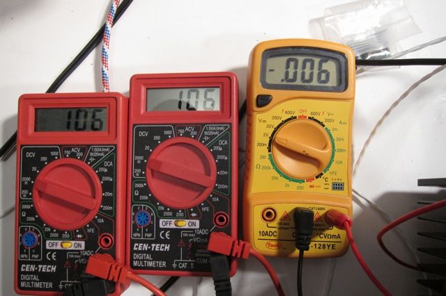
Full bias is 600mV (.6V) measured across a .47ohm source resistor.
So I put it down to a much lower level and see what can bee seen.
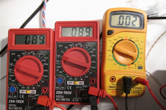
Meters are N channel bias, P channel bias and DC offset.
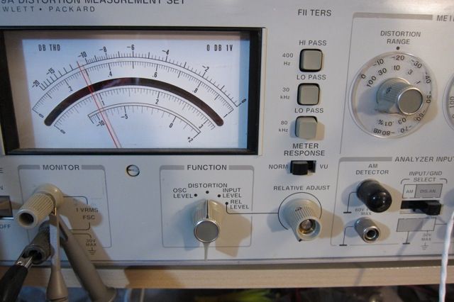
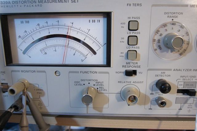
This is the distortion of 1K Hz, 1V input measured across a 8ohm resistor.
Please note that this is the 10% scale, and the THD is 2.9%
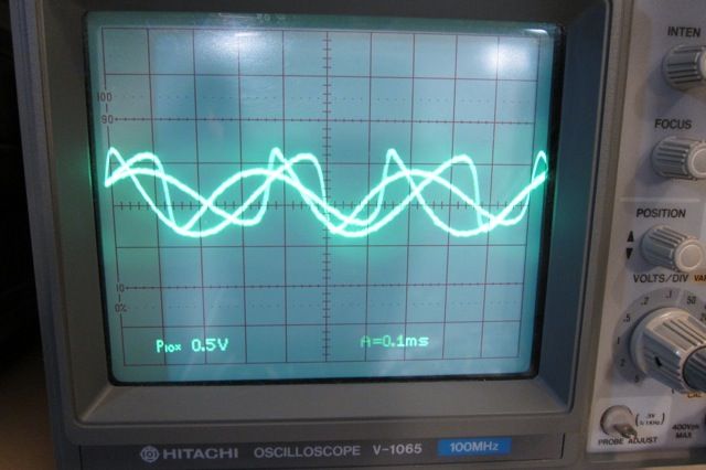
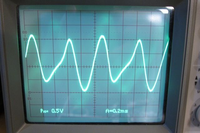
This is the distortion residual. I'm not sure what is causing the complex pattern, but I had to take a photo of it.
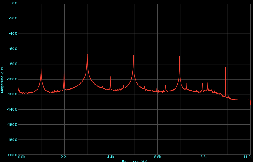
This is an FFT of the really weird residual.
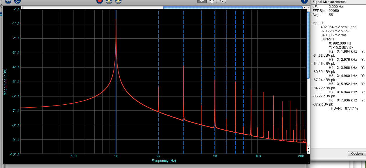
This is an FFT of the signal. In this and the above notice the really strong odd-order harmonics.
Last edited:
Increasing the bias a little bit has made the weirdness go away.
Distortion has jumped way down to .61%
The distortion residual is starting to look, well, better...
The FFT, although starting to look better with the proper shape and decreasing levels of higher fundamentals, is not that good.
Distortion has jumped way down to .61%
The distortion residual is starting to look, well, better...
The FFT, although starting to look better with the proper shape and decreasing levels of higher fundamentals, is not that good.
Tweaking up the bias to roughly 1/3 the suggested amount is starting to make things look much more normal.
Distortion is down to .24%
The residual is shaping together nicely.
Note how the 2nd and 3rd harmonics are the only things visible in this FFT. It's getting much better.
- Status
- This old topic is closed. If you want to reopen this topic, contact a moderator using the "Report Post" button.
- Home
- Amplifiers
- Pass Labs
- Some observations on bias vs. distortion