SY said:In low level stages, normally, yes. But the heaters should have some sort of ground reference and will preferably be elevated to some positive voltage above ground (someone suggested that before).
Sy-look at schmtc
")
Hi mod evil ,
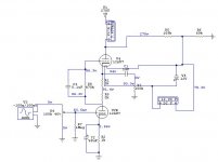
I have built ( and sold ) a LOT of this 12AU7 SRPP
configuration , and this is a quite simple preamplifier ,
with a very good tonal quality .
If you want that your assembly works properly , I’ll
try to give you some “tips” , that you should follow :
Obs : As your schematics “says” , V4 is the top triode
and V2b is the lower triode .
1 – The +B is correct ( 270 Volts )
2 – The heater bias is correct ( aprox. 70 Volts )
3 – Extract C1 ( 1 uf ) and R3 ( 100 K ) from the circuit
( they are in wrong position )
4 – Disconnect R1 ( 1K ) from the plate of V2b.
5 – Connect between the lower side of R1 ( 1K ) and the
plate of V2b , a 22 K x 2 Watts metal-film resistor .
The current that you had measured ( 6.134 mA ) is
VERY HIGH , the correct value is about 3 mA .
6 – Don’t connect the control grid of V4 , DIRECT to the
lower side of R1 ( 1K ) , use a 470 K x 1/4 Watt resis-
tor instead .
7 – Connect between the control grid of V4 and the plate
of V2b , a 0.1 uf x 400 V mylar capacitor ( It’s very
important , to by-pass the CCS with the AC signal )
8 – And finally , the MOST IMPORTANT .
As long as I could see , the source of hummmm in your
Preamplifier is the +B power supply , because you are
working with CCS ( the top tube V4 ) and this circuit is
very , very , sensible to any noise on the power supply .
Regarding TO SOLVE this problem , you need to build
a +B power supply that can deliver a LOT more than
the +B necessity of your circuit ( may be 350 Volts )
than you need to lower this value until the desired +B
voltage ( i.e. 270 V ) , using one or more sections of
RC filter . You can calculate the R value , simply
considering the circuit runing at correct current
value ( about 3 mA ) , so, each 1000 ohms , will lower
the +B value aprox. 3 Volts .
For the capacitor , you can use 150 or 220 uf x 400 V .
The further advantage is the high time constant , what
means that the +B will increase slowly , extending a LOT
the tube life .
Follow my tips , and let us know , if you were successful
Regards ,
Carlos
Hi Refference,
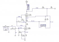
I have modified my schematic with yours instructions.
And I see on the simulation, when I put a 22k resistor I have 35v on the plate of V2B and 1.669ma of current.
I put a 2k on the place of 22k and I have 86.6v on the plate of V2B, and 3.669mA.
I put a print screen of the new schematic of the SRPP with your instructions to you confirm me if this is correct, okay?
To increase and decrease the B+ voltage, I'm thinking to make a regulator with a 2sc4923. I has found this NPN transistor in a CRT Monitor . This has a BIG Vceo voltage = 800v. But I haven't a good project of regulator with these NPN devices.
I put the B+ on the tube when the Filaments HOT...
Thanks and Best Regards,
Felipe Navarro.
Refference, In what part of São Paulo do you live? Do you know JUST TUBES BR yahoo list, this is a Yahoo list for Brasilians Tubes lovers...
I have modified my schematic with yours instructions.
And I see on the simulation, when I put a 22k resistor I have 35v on the plate of V2B and 1.669ma of current.
I put a 2k on the place of 22k and I have 86.6v on the plate of V2B, and 3.669mA.
I put a print screen of the new schematic of the SRPP with your instructions to you confirm me if this is correct, okay?
To increase and decrease the B+ voltage, I'm thinking to make a regulator with a 2sc4923. I has found this NPN transistor in a CRT Monitor
. This has a BIG Vceo voltage = 800v. But I haven't a good project of regulator with these NPN devices.I put the B+ on the tube when the Filaments HOT...
Thanks and Best Regards,
Felipe Navarro.
Refference, In what part of São Paulo do you live? Do you know JUST TUBES BR yahoo list, this is a Yahoo list for Brasilians Tubes lovers...
Attachments
Hi mod evil ,
You made some mistakes !!!
1 - The resistor R8 , should be connected between , the
control grid of V4 and the point between R1 and R9 ,
see my tip # 6 .
2 - C3 is connected correctly . OK !!
3 - R9 is wrong , its value is 22K , not 2K , see my tip # 5 .
4 - EXTRACT ( eliminate ) C1 and R3 from the circuit , they
must be ELIMINATED , see my tip # 3 .
5 – FORGET about +B regulated power supply !!!
It’s not necessary . The high time constant obtained
with a RC filter , is more than enough , to mantain the
+B value constant , see my tip # 8 .
Make the corrections above , redraw all the stuff
and try again !!!! I’m waiting your reply !!
Good luck ,
Carlos
Hi again mod evil ,
Now your circuit is OK !! You are almost there !!
ONLY ONE MORE “TIP”: If you change the value of
R1 and R2 from 1K to 1K2 , AND change the
value of R9 from 22K to 24K ( 2 x 12K series ),
the current will decrease a little bit and stay closer
to 3 mA ( the desired value ) .
The signal output will be taken from the CATHODE
of V4 ( this is a low impedance output ) . Connect
a mylar or polypropilene capacitor ( 2.2 uf or
4.7 uf x 400 V ) to the CATHODE of V4 ( the top
triode ) , and after the capacitor connect a 470K x
1/4 Watt resistor , to work like load , and “voilá”
that is the output .
Your 820 uf x 200v caps , are not useful , the correct
and the IDEAL solution is the follows :
1 – Try to get a power transformer with a 270 VAC
secondary , if you can not , try to use two power
trannys one at 220 VAC and other at 48 VAC
( secondary voltages ) series connected AND
IN THE SAME PHASE ( if not the voltages will
be subtracted , and not added , how should be )
2 – Rectify the AC with a bridge and filter with your
330 uf x 400 V cap .
3 – Then connect TWO 18 K x 3 Watts resistor ( one
for each channel ) at the 330 uf x 400 V cap , and
the other side of the resistors , you will connect
in TWO 220 uf x 400 V cap ( one cap for each
channel ) independently . Did you understand ?
Each 18 K x 3 Watts resistor , should be connected
to each 220 uf x 400 V , and .... “voilá” , at each
220 uf cap ( one for the left channel and the other
for the right channel ) , you will get aprox . 270 Volts
CC , WELL FILTERED , to feed the circuit , without
any hummmmm .
Try to make ALL the changes that I have suggested and
you will like the result . I’m shure !!!
Any doubt , you can ask !!!
Carlos
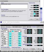
-> Refference,
I have evaluated the schematic in the TubeCad. And with 3mA, they send to me a mensage how I will have a BIG distortion because I have a low current on the plate, and this is will be a HIGH output impedance and Less gain.
I haven't money to buy a other power transformer. I'm a student with 15 years old.
See the file who I puted in this topic.
-> firefart_1st,
The problem isn't on the conections. Because I have shorted the input to the ground and the HMMM persists.
Attachments
Hi mod evil and Hi firefart ,
I’m tryng to transmit my humble experience , acquired
over 35 years working with tubes .
IT IS OBVIOUS THAT EVERY CONNECTION AND
WIRING , MUST BE SHIELDED , I DO NOT WANT
WASTE MINE AND YOURS TIME , TALKING ABOUT
THIS STUFF , THIS IS ABSOLUTELY OBVIOUS .
Mod evil , all information that I had sent to you , has like
base my OWN EXPERIENCE , and years of successful
working . If you want to trust me , good for you , your job
will be easier , if not , sorry at all .
About the transformer , you do not need to spend a
LOT of money , any power transformer , 24 + 24 Volts
x 250 or 500 mA , series connected with the 220 Volts
unity that you already has , is enough .
About the 220 uf x 400 V , is easy to get them in any
junk store .
About the money , I’m not a rich guy too , but you need
to have and to do , some sacrifice , if you want to get
the BEST when working with tubes .
Regards for all ,
Carlos
Hi Mr. Refference,
I have a transformer How I have retired from a Mini System. This transformer have a 18+18 and a 9v secundaries. With how many mA? I don't know. I think about 600 to 1200mA.
Your experiencie is more important for me. But I only asked for you, because this program is a refference for many users.
Are you asking to me put more one 220uf 400v capacitor on the power supply?
Best Regards,
Felipe Navarro
All Friends of DIYAUDIO,
I have remounted the SRPP with the last schematic who I post in here.
There aren't HMMM on this AMP.
But the problem. I think isn't on the my frist schematic. The problem is in the power supply. There aren't CRCRCR FILTERS ON THE FRIST SCHEMATIC. THIS IS GERATING THE PROBLEM OF HMMM.
This SRPP have a spetacular SOUND!
Best and Happy Regards,
Felipe Navarro
About energy
Damian,
I speak in here now about energy...
My amplifiers are OPA549 with a peculiar power supply.
I have tested some uncommon snubbers and filters. My power supply in the OPA549 have many 68uf, 4.7 + 100ohm, 1pf, 0.22uf and 0.1uf in the paralel of the 4700uf capacitors, these small capacitors are used, but brand new!
After this Episode with HMMM, I THINK, THE ENERGY IS THE SECRET TO A GOOD AMP AND A GOOD SOUND.
Thanks for all replys.
Thanks for all helps.
Thanks for all readers.
Best Regards for all peoples
- Status
- This old topic is closed. If you want to reopen this topic, contact a moderator using the "Report Post" button.
- Home
- Amplifiers
- Tubes / Valves
- Some HMMM on my SRPP