That is only one small part of what engineering is about where I come from.
Let me go back and set this in context. The OP stated he had a transformer which he wanted to use. You'd suggested he needed to change that trafo to either higher or lower voltage. I'm saying and demonstrating there's no reason for him to do so, his original suggestion is absolutely fine.
Also the definition of optimum use of ressources seems to be different where you live and/or work. Here it is to design as exactly as possible for the necessary power.
No, we have a transformer and 4 chips. I'm saying the existing design is pretty much the best use of those resources. You were saying otherwise -but I've noticed you've dropped your claim that the 2+2 configuration would be current limited. So perhaps now you're not arguing what you originally were?
Designing for the highest possible power without need is considered a waste of ressources.
I agree, but that's not what's happening in this case.
If the amplifier is limited anyhow, what does it matter which is the limiting factor as long as there is enough power?
In this case, we don't have a spec for the power, we have 4 chips and were discussing the best way to utilise them. You suggested 4 in parallel and the original configuration is 2 + 2.
That is certainly not the solution with your definition of an ideal load, because that would lead to the highest possible dissipation.
I cannot follow your argument here.
I've noticed you've dropped your claim that the 2+2 configuration would be current limited.
I haven't. I stopped mentioning it, because I don't see what difference it makes. The amp board and transformer combined will for sure work into a 6 or 8 Ohm load. They will work into a 4 Ohm load depending on the way it is used. I am convinced that the thermal limit is a much more determining factor than voltage or current clipping in such a setup.
In this case, where the components are already at hand, the most efficient way to go about it is to simply try it out. And then not to be disappointed when this high power amp can only be used at low output power in the long run lest the protection kicks in.
I haven't. I stopped mentioning it, because I don't see what difference it makes.
I can't understand why you brought it up if you don't see the difference it makes. Did I make some mistake in showing that the current limit won't be exceeded?
The amp board and transformer combined will for sure work into a 6 or 8 Ohm load. They will work into a 4 Ohm load depending on the way it is used. I am convinced that the thermal limit is a much more determining factor than voltage or current clipping in such a setup.
Yet you proposed a configuration which was voltage limited. My point is that its better to design for power (thermal) limitation too.
In this case, where the components are already at hand, the most efficient way to go about it is to simply try it out. And then not to be disappointed when this high power amp can only be used at low output power in the long run lest the protection kicks in.
So that's cool, we have consensus. sardonx don't change your transformer, pacificblue says its fine to try out the one you already have.

Yes.Did I make some mistake in showing that the current limit won't be exceeded?
A speaker is not a resistor. The impedance will dip below the nominal impedance, meaning more current (up to 25 %) will be needed at certain frequencies. The current limit would be exceeded there.
The current limit of 6,5 A is given at 25 °C. As the IC temperature rises the threshold will go down and that new lower current limit would be exceeded.
And mine is that a design for thermal limitation is not superior to a design for any other limitation.Yet you proposed a configuration which was voltage limited. My point is that its better to design for power (thermal) limitation too.
A chip amp that reaches its voltage limit will distort. The user can reduce the volume, the distortion goes away and the amp will remain intact.
A chip amp that reaches its thermal limit will switch off, if the protection circuit reacts fast enough. There are enough blown TDAs around to show that it does not always react fast enough. So there is a certain potential that the amp wil blow.
sardonx don't change your transformer, pacificblue says its fine to try out the one you already have.
What a cute comment. Remind me to laugh, when I have some time to spare.
A speaker is not a resistor. The impedance will dip below the nominal impedance, meaning more current (up to 25 %) will be needed at certain frequencies. The current limit would be exceeded there.
The current limit of 6,5 A is given at 25 °C. As the IC temperature rises the threshold will go down and that new lower current limit would be exceeded.
All good points and I agree. So this may be language barrier again, because you originally said 'with 4 ohm'. To me that meant a resistor. Since the speaker is unknown I've always been comparing the two topologies with a resistive load.
And mine is that a design for thermal limitation is not superior to a design for any other limitation.
Let's agree to disagree on this then eh? I'm saying it makes better use of resource to aim for thermal limitation.
A chip amp that reaches its voltage limit will distort. The user can reduce the volume, the distortion goes away and the amp will remain intact.
No disagreement.
A chip amp that reaches its thermal limit will switch off, if the protection circuit reacts fast enough. There are enough blown TDAs around to show that it does not always react fast enough. So there is a certain potential that the amp wil blow.
Have not found this in my experience. Simply because there are blown up TDAs around does not mean they blew up because of reaching their thermal limit. There are other ways to blow up chips.
What a cute comment. Remind me to laugh, when I have some time to spare.
I find this comment so cute - that laughter would not be a spontaneous thing for you, but you schedule it.
I wish I trully understood better what you guys were talking about! If it helps at all the speaker I will be using is an usher 8948a/9950 design that by description and graph has a benign impedance that doesn't drop below 6 ohms really. I am however using an MLTL instead of the proposed bass reflex. I may try other speakers in the mean time though if i don't get them done by the time the amp arrives.. the speakers have only been on hold for a year now! Now to find some huge aluminum slabs for the heatsinks..
OK.. I will keep the transformer
OK.. I will keep the transformer
All the more reason to stick with an amp that gives you a good voltage swing, having a speaker that's above 4R. When choosing heatsinks, go for black anodised as they radiate much better. Untreated aluminium is pretty lousy as a heatsink despite its good thermal conductivity.
Has anyone got one of these yet and had a decent go with it?
I am needing more power for the bottom half of my bi-amped setup, and am thinking of getting some of these and finding a transformer, but adding it up with their not combining shipping and other parts is really close to the price of a cheap power amp so if there is any doubt of their quality I will not go there..
I am needing more power for the bottom half of my bi-amped setup, and am thinking of getting some of these and finding a transformer, but adding it up with their not combining shipping and other parts is really close to the price of a cheap power amp so if there is any doubt of their quality I will not go there..
Well it's been a little delayed but i did get the boards and they are basically what's in the picture. Haven't really compared too critically though. The bad news is when powered up there was a quick buzzing sound and then nothing. No sound whatsoever coming out of the speakers even with my ear right up to the tweeter. So i think they are dead. I did have them at a shop so the machinist could machine out spaces out of big blocks of aluminum for them so he could have damaged them I suppose but unlikely both of them. The rails both read 30.8 volts when everything is hooked up. Even when it's plugged in with signal going through them and hooked up to speakers for about a minute (haven't kept it on for longer) the chips don't change temperature at all.. cold. So I guess they're effed up? Anyone got any ideas?
Pacificblue,
I didn't check that. The board only has v-, v+, ground inputs for voltage.
Before i get to that though, here are a few things that are baffling me:
1. Last night the power supply rails were reading 28-30 volts with the supply disconnected from the boards. Normal. Right now they are reading around 42-43 volts. How can that be?
2. While hooked into the board last night at the same time, and checking the rails at the board input i was getting a reading of only a few volts. 3-4 maybe..
How can the power supply fluctuate like that? It's possible the filter caps are damaged. They did overheat severely once for a few seconds while building a different power supply due to wrong wiring. I unplugged it quickly though, they didn't burst, swell, or leak anything so i figured they are fine. Can this be responsible for the power jump though?
I certainly hope it's the mute or standby pins. But if 42 volts was what went into the board it's probably fried right?
It's possible the filter caps are damaged. They did overheat severely once for a few seconds while building a different power supply due to wrong wiring.
It is possible that the caps are damaged.
I certainly hope it's the mute or standby pins. But if 42 volts was what went into the board it's probably fried right?
No, the TDA7293 can withstand 120 V from rail to rail. Check the voltage rating of the capacitors on the board. A slight overvoltage won't kill them immediately either, but if they are rated for much less then 42 V, they might have been damaged.
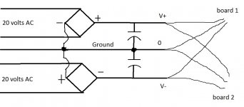
Anyhow the 20 V AC should give 28-30 V with no load, so you should expect to get 56-60 V from V- to V+.
Ok, let me recap. Connecting voltmeter from v- to v+ with no load, after the rectifiers/capacitors i'm getting around 48 volts (not 42, sorry). Connecting from ground to v+ i'm getting 30. Does this make sense?
Only, if you have 18 V from V- to ground. That would indeed hint at damaged capacitors or a still existing wiring error in the negative power supply.
Just checked again this moment. From 0V to -V I'm getting exactly 30.0 V. From 0V to +V I'm getting 28.9 V. From -V to +V i'm getting 47.1 V.
The capacitors are rated 80 VDC
Its' wired the way it is in the picture, no doubt about it. So i guess i'll get some new caps. Too bad, these ones were $60 a piece
The capacitors are rated 80 VDC
Its' wired the way it is in the picture, no doubt about it. So i guess i'll get some new caps. Too bad, these ones were $60 a piece
Yeah.. I don't know what it was. I bought some new caps and rewired the whole thing and got the correct voltage. 60 V exactly. However, one of the chips on one board fried immediately after plug in. And the other board was just putting out some noise through the speaker.. hmmm. I will have to order another pair of boards and have a go at this once more. Will update then..
I haven't inquired about it to be honest. There is DOA policy which you have to report within a few days of receiving the product but that wasn't possible in my case since i had to wait longer than that to get the heat sinks made. But I will send them a message. I just don't want them to give me some answer that will **** me off and stop me from buying another pair lol.. the aluminum slabs are predrilled already for the chips. For the price it's worth another try.. around $70 shipped and assembled pair. The one chip is dead and i'm not getting into ordering one and replacing it. So I will have to order at least one more board. Whether they decide to take the blame for it or not i dont know. I have my doubts. We'll see.
I love them !
Hi there,
I had build a Newtronics TDA 7293, but managed to blow the board twice,
with expensive Newtronics boards. The last time it took so long to get a
replacement board that I was getting tired of waiting, so I decided to get the
chinese items discussed in this thread and juts mount them to what I had:
45 V input ! This gives 90 V from + to - ! I am using an
iMac with Apple Lossless music files
a Terratec 192/24 X24 Firewire Soundcard
a Ermax Pro Headphone Amp (as preamp)
a clone Krell chassis with Newtronics internals, but the boards replaced by the cheep chinese ones, in addition I added control using two DACT CT2.
a pair of QUAD 989 (with all panels replaced by myself)
all cables are semi-professional quality (around 50 Euro each), but I do not believe in cable vodoo, just wanted to make sure that there is no problem...
Sound is now equal to my benchmark (AKG 501 headphones).
If anyone has any suggestion on improving sound quality, please let me know.
- Status
- This old topic is closed. If you want to reopen this topic, contact a moderator using the "Report Post" button.
- Home
- Amplifiers
- Chip Amps
- some help on TDA7293 boards off Ebay