for what it's worth, I am aware of power supply sag, and the effect it has on this whole topic. I am just trying to understand this in an "ideal sagless amplifier" sense.
even for tube guitar amps, this psu sag is one reason for the "sound" of a particular amp....some would replace a 5ar4 or even a 5u4 with a 5y3 to get that sonic signature they want...still some deliberately undersized the output traffo.....i used the cheapest core material there is for the sound some guitarist were after....

IMO it's a bit pessimistic to suggest that calculation is not useful when determining the output of an amplifier.
calculation is useful anytime, but what to do with the results that is the thing, do you take it with a grain of salt knowing that it is not an end by itself but just a beginning?
@ Tony - the Quad 303, of course, has a regulated supply rail with tons of headroom across the regulator - 88V regulated to 67V if I remember rightly (tho apparently Peter Walker of Quad admitted to D Self years later that this was unnecessary, and a result of Quad's over-caution in it's first bjt power amplifier design).
yes, building an amp with regulated rails gets you 0db headroom.....and the fact that you are in fact building two amplifiers per channel.....
I use solid state rectification, but the amp I gig with has a large resistor keeping my screens 100V lower than my plates in an attempt to keep output power down. I get a little bonus sag from it, but its mostly a pretty snappy amp.
Valve guitar amps are soooo much easier for me than solid state hi fi has been. Not sure why this is. I designed my current amp from scratch and feel I have a pretty good handle on the ins and outs of it. Even the output power calculations. That's what's so funny about this thread.
Never having dealt with a split supply before has caused me to be back at square one in many regards. There are nodes in a solid state amp with split supplies where I really don't know how to figure what the quiescent voltage should be. Take a single transistor VAS loaded by a constant current source. I can't figure fore the life of me what the collector voltage in that situation should be if I don't have the usual bias spreader in that position. People have told me its "undefined"
solid state circuit analysis does not differ much from tubes, if you keep in mind that tubes are normally conducting devices in the absence of control grid bias volage, whereas bjt's are normally non conducting in the absence of input voltage....
btw, the amp i posted above is about 20 years old and is due for rehab...
and one more, there is no pnp tube equivalent...
btw, the amp i posted above is about 20 years old and is due for rehab...
and one more, there is no pnp tube equivalent...
Actually may I ask a design question here as well, it is something basic I am confused about. I purchased Vogel's book How to Gain Gain, which is pretty good and it is pretty much all maths.
He goes through every conceivable valve circuit from cathode follower, grounded grid cascode, aikaido, SRPP etc. and examines each in turn calculating all values including input impedance, output impedance, output current etc.
He also presents the transfer functions for the circuits etc and Bode plots.
NOW I am beginning to suffer from not being able to see the wood for the trees!
When you are joining two separate stages .. is the basic aim to match the output impedance from one to the input impedance of the next for maximum transfer of power whilst also trying to get enough current onto the grid of the next stage to drive the next valve ... therefore the amp is designed from back to front .. start with power valves and work your way back ? Is that the overall design procedure ? This would be the same for transistors also ?
Thanks
tony, do you use Spice to get a basic design started to give you a rough idea etc, or all calcs by hand ?
Can you use Spice for that ..ie. for valves ?
no i am not into spice...i do calculations by hand....
If anyone is interested enough to follow the details of JM Fahey's explanation in post #57, I have an LTSpice model of the Quad 303. This was my first attempt to model with LTSpice, so it may be a bit crude for the experts. There were two basic versions of the 303, the later one with a re-worked bias spreader arrangement - which is the version in this model. The model includes two stereo channels. I have played around with component values at various times, but I think the attached is a reasonable working model.
I know, don't tell me, this design is now nearly 50 years old, and "out of the ark" by current standards (old faithful transistors and single polarity power supply), but it is still reasonably respected, and nice and simple for illustrative purposes. Also, LTSpice may not be the best simulator around, but it is free!
I know, don't tell me, this design is now nearly 50 years old, and "out of the ark" by current standards (old faithful transistors and single polarity power supply), but it is still reasonably respected, and nice and simple for illustrative purposes. Also, LTSpice may not be the best simulator around, but it is free!
Attachments
Last edited:
Single polarity supply isn't a problem performance wise. It actually has benefits in some ways. So the Quad is old and has a single ended (rather than differential input stage), but the result of that is the distortion produced is predominantly even harmonic, pleasing to the ear. So that can be a huge plus for sonics. The output stage uses NPN devices for both outputs rather than an NPN and PNP device in what is known as a quasi-complementary configuration. That to emphasises even over odd distortion.
So sonically this type of circuit has a lot going for it.
I'll have a look at your file shortly
and has a single ended (rather than differential input stage), but the result of that is the distortion produced is predominantly even harmonic, pleasing to the ear. So that can be a huge plus for sonics. The output stage uses NPN devices for both outputs rather than an NPN and PNP device in what is known as a quasi-complementary configuration. That to emphasises even over odd distortion. So sonically this type of circuit has a lot going for it.
I'll have a look at your file shortly
You've gone to a lot of trouble putting the complete circuit into spice.
I keep saying I'm no expert on simulation but I've learnt quite a bit over the last year or so. Circuits with time constants (all the large electros) are problematic and really skew the results of things like FFT plots. There are work arounds to that.
I would concentrate on simulating just one channel of the power amp and do a full set of results such as distortion at 1watt and full output at say 1 and 10Khz. Squarewave testing could be interesting too. I would also use more up to date devices and probably use Bob Cordells models which seem universally well received.
For practical simulation purposes, I just use one channel of this model - I only included both for completeness.
Many people say that you need to be really careful about unintended consequences if thinking about updating the output devices - apparently higher spec devices can increase the risk of instability, and even using later versions of 2N3055 (with higher f response) can cause problems. It has been suggested that those older devices have a lot to do with the 303's reputation for being "bombproof".
As a beginner with Spice, I will have to work on simulation testing. I can't even get a sensible reading for power dissipation in the 8R output load resistor - not sure whether that's result of my ineptitude or shortcomings in LTSpice (maybe it can only cope with DC dissipation).
There is some truth in modern devices causing problems but its very application specific. Looking at the circuit I would say the Quads performance is really dictated by the passives. I wouldn't forsee much of an issue tbh.
For the power dissipation in a part try "ALT" and clicking the resistor in question.
If your interested I'll see what I can come up with as a simulation for the Quad. Its all good experience
For the power dissipation in a part try "ALT" and clicking the resistor in question.
If your interested I'll see what I can come up with as a simulation for the Quad. Its all good experience
Yes, ALT + click plots the power waveform. Thanks for that - I knew there is a way of doing it, just couldn't remember.
I would certainly be interested in your simulation model, if you you have time/inclination to do it. Mine is pretty basic - I found the xistor models in random places by googling (I've heard that some manufacturers aren't too careful about putting them together). I have just used the basic LTSpice models for everything else. I believe there might be sub-circuit models for potentiometers, etc, but it was far less hassle for me to just represent them with two resistors, and get to the right values by iteration of different values until I got within a fraction of a percent of the required voltages.
I would certainly be interested in your simulation model, if you you have time/inclination to do it. Mine is pretty basic - I found the xistor models in random places by googling (I've heard that some manufacturers aren't too careful about putting them together). I have just used the basic LTSpice models for everything else. I believe there might be sub-circuit models for potentiometers, etc, but it was far less hassle for me to just represent them with two resistors, and get to the right values by iteration of different values until I got within a fraction of a percent of the required voltages.
Spice is fine ... but there's a nice "between point" that uses spreadsheet calculation instead. That's generally what I use. Even that would make old-timers (who are getting quite old indeed!) shake their heads. We have to remember that virtually every circuit designed before computers (i.e. before the mid 1970s) had its circuit component values calculated with slide rules and notebooks. Nice big Picketts (the "Cadillac" of slip-sticks), but the Japanese bamboo jobs were even more cool.
Pickett may be "Cadillac", why not?, but Staedtler is "Mercedes Benz" or "Porsche".

I started Engineering in 1969 and Slide Rules were the only game in town ... unless you begged for Computer time and got an hour at the IBM 1620.
No monitor screen, of course; input was by Teletype (a sort of electric typewriter) or punched paper tape and output was printed on blanket sized zig zag paper.
So the preferred option was the slide rule.
Hey!!, even futuristic Star Trek people used them!!!

And Isaac Asimov depicts people using them in the Year 5000 something !!!
I started Engineering in 1969 and Slide Rules were the only game in town ... unless you begged for Computer time and got an hour at the IBM 1620.
No monitor screen, of course; input was by Teletype (a sort of electric typewriter) or punched paper tape and output was printed on blanket sized zig zag paper.
So the preferred option was the slide rule.
Hey!!, even futuristic Star Trek people used them!!!
And Isaac Asimov depicts people using them in the Year 5000 something !!!
God, how we oldies have suffered! Back in 1970, it was slide-rule, or logarithm tables, or nothing. A simple resonance calculation would take an occasional dabbler like me 10 minutes to crack. I struggled to afford a (functionally very basic) Sinclair calculator kit in 1975, but within just a few more years a respectably good scientific calculator could be bought in any High Street for the cost of a couple of meals-out. But I don't miss all that - Spice does all the work and remembers those formulae for you - provided you know what the limitations are.
Last edited:
OK, here we go...
The "Quad 303" file is using standard spice library models.
The "Quad 303 using Cordell models" file uses models by Bob Cordell. The diodes must have a slightly different forward volt drop to the original Quad parts. This needs the addition of R29 (72 ohm) to generate slightly more volt drop. Without this the quiescent current can't be set high enough (5 to 10ma).
The "Quad 303 optimised" file is prepared for simulation.
Notice how I have removed the input coupling cap for simulation by adding an offset voltage to exactly match the voltage that was on this cap. A voltage source has replaced the resistive divider and 300uf cap. The 50uf bootstrap cap has been reduced to 1uf. As we are not testing at low frequencies this is acceptable.
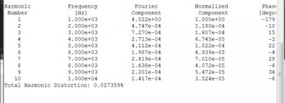
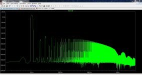
Quad 303 distortion at 1 watt show distortion and FFT. For the FFT plot increase the number of cycles (the input signal) to 1600 and the .tran command to 800ms. Look at the last 8 cycles by starting the FFT at 792ms and ending at 800ms. The distortion (spectrum) isn't as "good" as I thought it might have been.
The "Quad 303" file is using standard spice library models.
The "Quad 303 using Cordell models" file uses models by Bob Cordell. The diodes must have a slightly different forward volt drop to the original Quad parts. This needs the addition of R29 (72 ohm) to generate slightly more volt drop. Without this the quiescent current can't be set high enough (5 to 10ma).
The "Quad 303 optimised" file is prepared for simulation.
Notice how I have removed the input coupling cap for simulation by adding an offset voltage to exactly match the voltage that was on this cap. A voltage source has replaced the resistive divider and 300uf cap. The 50uf bootstrap cap has been reduced to 1uf. As we are not testing at low frequencies this is acceptable.
Quad 303 distortion at 1 watt show distortion and FFT. For the FFT plot increase the number of cycles (the input signal) to 1600 and the .tran command to 800ms. Look at the last 8 cycles by starting the FFT at 792ms and ending at 800ms. The distortion (spectrum) isn't as "good" as I thought it might have been.
Attachments
- Status
- This old topic is closed. If you want to reopen this topic, contact a moderator using the "Report Post" button.
- Home
- Amplifiers
- Solid State
- Some dumb rookie questions about output power