i just repaired a receiver that had had one of the front channel outputs (with signal) shorted to one of the surround channels (with no signal), and the surround channel acted as a "virtual ground". guess what.... both channels were blown. so if you do the "tug of war" thing. make sure you have a load connected between the two...
a few notes about sims...
a) the old addage "trust, but verify".... it may work in a sim, but you don't know for sure unless you build it.
b) some device models are garbage, and leave out some parameters that won't show up until you build a working circuit.
c) simmed components don't smoke. you can "sim" a 500W output stage with a 2N2222 and 2N2907, and it will work in the sim, but will turn to smoke and fire in real life.
d) voltage sources in a sim are ZERO output impedance, in real life they are not
e) unless you take the time to create variations in components, all components are 0% tolerance, and all transistors are perfectly matched in a sim. in real life, the component values are all over the map.
JCX- believe what you want. Your "SIMs" are almost a complete waste of time and worthless...
sounds like you recognize you've lost the argument on theory, practical engineering estimates of "microphone effect" magnitude and feel the need for a fall back
I assume anyone with any knowledge at all of electronics, interconnect will recognize you can’t get uOhm impedance at output terminals, or the ends of speaker wire
that you do need to adjust real world measurements for layout, wiring, any common path impedance coupling
but would recognize that the feedback amplifier principles do work, that a high feedback amp is controlling the V across the feedback R as closely as system noise, gain limits allow
audio frequency loudspeaker "back EMF" or "microphone current" simply are not practical issues in audio amp design beyond sizing the amp output for worst case current demand
which can easily be several times (max estimate of 6.6x for multiway) higher than the speaker's name plate impedance rating for certain bizarre test waveforms - again this "conventional" audio amplifier engineering now that you can find the warnings, waveforms, peak factors in Self, Cordell's books – for “back EMF” coupled complex terminal impedance, XO impedances
it is a total waste of time to harp on dynamic “loudspeaker as microphone” currents as a “problem” in practical audio amp designs
it is hard to get paid for "just sims" - I have built, measured, meet objective performance specs in my designs for scientific/industrial measurement products - including strain gage products that look at the output of Av 8000 amps with 16 bit converters into the kHz – on single boards including 40 MHz DSP, x86 single chip processor and ethernet output - with transducers at the end of 50 ft cables - I am familiar with a few real world measurement issues
sims are easy to share, allow making impractical "measurements" that clearly illustrate theory
making uOhm measurements put you up against lots of implementation issues - even Self discusses how you can mess up layout/wiring of the feedback take-off "point" in a amp
but the real world results of feedback theory can be seen indirectly and are supported by measurement down to those levels
I believe DIY audio should have some method for SIM heads to be segregated from people who actually build and test real circuits...
A scurrilous, if indirect, personal attack increasingly common here and piece of intellectual dishonesty – can be taken several ways – there seems to be a agenda at work – audiophile ”Gurus” seem to feel a need to “protect” others from interpretations of EE theory applied to audio
I try to illustrate “useful theory” – that I have found helpful over decades of engineering employment
"There is nothing so practical as a good theory."
Last edited:
jcx- nothing you say above has anything much to do with real amp design for audo. I am not attacking you other than those mostly worthless sims for audio you and so many others pretend have deep significance. The constraints for strain gauges fade to insignificance compared to audio so fail to see the point there so perhaps you can explain to all why a purely resistive stain gauge should be of interest to those driving loads and sources such as the subject of this thread, the other channel. The notion dealing with resistive elements such as a strain gauge in any way compares to the use of transistors of many tens of megahertz bandwidth into loads which act as sources is folly. I see the support of theory is your anchor but that has a lot less to do with reality as by definition theory is at best a simplified model. S parameters describe how a transistor behaves in circuits above DC and are not likely be be included in your sim which exactly means input and output impedances cannot be correctly calculated beyond near DC frequencies. Sims are almost novelties which have elevated the newbie or amateur to supposed levels of expertise which are likewise not valid. For the design professional sims are useful tools after careful calibration which can lead insight into certain circuit behaviors but as most good engineers know well is not even close to the whole story. Sims are least useful when currents exceed about one amp.
The subject of this thread is amps and bad, reactive loads, and loads which act as sources as a real world test base in this case named "tug of war." This has little to nothing to do with sims therefore, sims have little place in this thread.
As for micro-ohms, see my micro ohm output amp:
http://www.diyaudio.com/forums/chip-amps/163385-so-just-how-good-can-chip-amp-9.html
One of the uses of theory in engineering analysis is to give perspective, estimate magnitude of effects, order concerns - this "loudspeaker as microphone back EMF source" has appeared in other threads, in the context of a paradigm destroying "hit" against "conventional audio engineers", feedback analysis
I would like to not have to address this irrelevancy in every thread, there's no point in detailed theoretic and measurement arguments when it is simply mouthed by a "audiophoolish" fanboy - but getting a competent engineer to admit its relative irrelevance would potentially help move the general level of discussion forward
Summa, slightly less overblown than your last post but I still see some lack of perspective, respect for logical application of engineering principles
you also keep sabotaging your own point by introducing new mischaracterizations while trying to support your position/bolster your perceived authority or deflect the central logical thread of the argument
the "DC" Spice model claim limitation is simply wrong - nonlinear device capacitances, charge storage, carrier transit time effects are included in Spice transistor models - getting good values for real devices is difficult, simplified "default" param are often seen in manufacturer's models - Andy C, Bob Cordell have done some work on audio power Q models for us
the S parameter formalism is used where EM propagation effects become significant, audio amps, transistors, circuit models seldom employ S parameter methods for the very good reason that we don't need them for excellent audio frequency accuracy or adequate stability modeling of the typical audio amp Global loop
even local RF oscillation can be explored with partial mutual inductance, parasitic C trace/package/build geometry models in Spice
try using the Goolgle search for this site, “s parameter” –“T/S” gets 16 posts – despite the diversity of education/expertise/opinion here there doesn’t seem much interest in S parameters for audio
and you keep with the strawman projection that some/anyone ever takes Spice sims as some golden ideal above hardware rather than as just one tool in the engineers design toolbox with strengths, weaknesses
but to return to the argument I am making – your claim
may be “true” but is a insignificant consideration in audio amp design, still laughable
your own “example” was ~500 mV signal from a unterminated woofer-woofer coupling at a room mode
if you want to actually address the discussion could you explain:
I would like to not have to address this irrelevancy in every thread, there's no point in detailed theoretic and measurement arguments when it is simply mouthed by a "audiophoolish" fanboy - but getting a competent engineer to admit its relative irrelevance would potentially help move the general level of discussion forward
Summa, slightly less overblown than your last post but I still see some lack of perspective, respect for logical application of engineering principles
you also keep sabotaging your own point by introducing new mischaracterizations while trying to support your position/bolster your perceived authority or deflect the central logical thread of the argument
the "DC" Spice model claim limitation is simply wrong - nonlinear device capacitances, charge storage, carrier transit time effects are included in Spice transistor models - getting good values for real devices is difficult, simplified "default" param are often seen in manufacturer's models - Andy C, Bob Cordell have done some work on audio power Q models for us
the S parameter formalism is used where EM propagation effects become significant, audio amps, transistors, circuit models seldom employ S parameter methods for the very good reason that we don't need them for excellent audio frequency accuracy or adequate stability modeling of the typical audio amp Global loop
even local RF oscillation can be explored with partial mutual inductance, parasitic C trace/package/build geometry models in Spice
try using the Goolgle search for this site, “s parameter” –“T/S” gets 16 posts – despite the diversity of education/expertise/opinion here there doesn’t seem much interest in S parameters for audio
and you keep with the strawman projection that some/anyone ever takes Spice sims as some golden ideal above hardware rather than as just one tool in the engineers design toolbox with strengths, weaknesses
but to return to the argument I am making – your claim
In stereo speakers the left speaker produces sound which drives the right speaker acoustically and thereby produces an electrical signal in the transducer which then is applied to the inverting input of the feedback amplifier. Loudspeakers are more than loads. Loudspeakers are sources of signals. Generators if you will.
may be “true” but is a insignificant consideration in audio amp design, still laughable
your own “example” was ~500 mV signal from a unterminated woofer-woofer coupling at a room mode
if you want to actually address the discussion could you explain:
how does an s-parameter analysis help? - at woofer/room resonance frequency?Further, many amps will pass a lot of current but make extremely lousy virtual grounds. To simplify, at the output terminals low output impedance and an amazingly high input impedance. Now I know this sounds out of balance and that is exactly how many amplifiers and other power supplies behave.
measurements require interpretation, which requires theory - a measurement without a model of the system doesn't "say" anything about how to improve a circuit
sorry it has gotten so confrontational but you are not apparently willing to discuss the ideas
diy audio so far hasn't embraced censorship of ideas
sorry it has gotten so confrontational but you are not apparently willing to discuss the ideas
diy audio so far hasn't embraced censorship of ideas
Seems to me jcx has offered to come forward and present his audio amplifier design along with his uncalibrated simulation and demonstrate via direct measurement of the real amplifier and simulation calculated results how well the simulation predicts the laboratory measured values for his real amplifier. This would include items such as THD, bode plot including phase margin under resistive and reactive loads, open loop and closed loop gain profiles, slew rate, current output, output impedance, input impedance at the output terminals and any other measurement common to an audio power amplifier. With this jcx can show us all how well the simulation matches his real world amplifier.
Actually, it seems very likely jcx has already done all this work as jcx is quite certain these match very well so one must assume this work has already been completed. We simply await the post containing the simulation versus the real amplifier test result.
Please show us all jcx. Upload as many details as you can to prove your point about uncalibrated simulations. We await the results of your wisdom and knowledge!
Seems to me jcx has offered to come forward and present his audio amplifier design along with his uncalibrated simulation and demonstrate via direct measurement of the real amplifier and simulation calculated results how well the simulation predicts the laboratory measured values for his real amplifier. This would include items such as THD, bode plot including phase margin under resistive and reactive loads, open loop and closed loop gain profiles, slew rate, current output, output impedance, input impedance at the output terminals and any other measurement common to an audio power amplifier. With this jcx can show us all how well the simulation matches his real world amplifier.
For power amplifiers , wich have really low device count compared
to other items , simulations are quite accurate to the point of being
trivial.
Modern processors wich exceed the billion transistor mark are only
simulated , not built to be tested , only the final mask will be manufactured,
all the work before this step was done using simulation of all the different
parts , logicaly, and electricaly using the spice models provided by the foundries.
I really don't want to run a school on deconstructng bad rhetoric
classic deflection tactic - Again
what part of actually intelligently discussing ideas do you not understand?
throwing out any objection whatsoever that you think might "stick" however a misrepresentation or outright fabrication on your part is not
just to set the record straight: I have never beaten my wife
the whole premise of “Spice accuracy” is a Strawman
I specifically claimed free manufacturers Q, op amp models are not accurate, do not allow predicting any particular physical piece of hardware performance to any specific level of accuracy
I did mention Cordell's improved models of popular transistors - you could try crediting me with having read chapter 20 of his book - have you?
elsewhere I have been early in discussion of Spice modeling accuracy to point out that lack of "live" device temperature modeling
even provoked a AD engineer to post here when I pointed out the errors in his op amp macromodeling modeling
Seems to me jcx has offered...
classic deflection tactic - Again
what part of actually intelligently discussing ideas do you not understand?
throwing out any objection whatsoever that you think might "stick" however a misrepresentation or outright fabrication on your part is not
just to set the record straight: I have never beaten my wife
the whole premise of “Spice accuracy” is a Strawman
I specifically claimed free manufacturers Q, op amp models are not accurate, do not allow predicting any particular physical piece of hardware performance to any specific level of accuracy
I did mention Cordell's improved models of popular transistors - you could try crediting me with having read chapter 20 of his book - have you?
elsewhere I have been early in discussion of Spice modeling accuracy to point out that lack of "live" device temperature modeling
even provoked a AD engineer to post here when I pointed out the errors in his op amp macromodeling modeling
Last edited:
[snip] Further, many amps will pass a lot of current but make extremely lousy virtual grounds. To simplify, at the output terminals low output impedance and an amazingly high input impedance. [snip].
Huh? How is that possible? How can something be a high impedance and a low at the same time?
Do you have any tech arguments to explain it?
I routinely measure my amps' performance in this area by pumping current into the output. When the amp has sufficiently low Zout, it eats up anything I pump into it.
jan didden
I don't think the technique is totally useless, looking at the theory helps understand what it can tell us
with low Z output amps you do have a correspondingly small signal at the output - do the calc for the S/N
which is part of my point in objecting to the apparent concern with “loudspeaker as microphone back EMF” injected signal – its just too small a current, too small of a“disturbance” of the amplifier output for reasonable assumptions for a home listening loudspeaker/room situation
but for larger test currents, justifiable as predicted or measured loudspeaker phase shifted and nonlinear current demands you could have useable S/N, possibly be able to measure "interesting" distortions
the fact that holding the output at gnd and injecting current is not sensitive to some distortion causes could be helpful
and you can use high amplification at the "virtual gnd" amp output since you don't have the Vswing that you would have at the same current in the forward operation into a load
or if you only have a single frequency notch filter in your toolbox you can do output injected IMD testing with the forward signal at your notch frequency and the injected signal at some other frequency (or sweep)
by understanding what you would expect see by driving the amp to the same output current into a load in the "forward" direction you can isolate some causes of some observed distortions by seeing where the measurements differ
Last edited:
I am also very tired of this theoretical discussion.
As a laboratory fact I have personally measured hundreds of power amplifiers on calibrated equipment and have yet to find one example which shows output impedance to be very similar to input impedance at the output terminals. These two are always frequency dependent and have not been found to be anywhere near equal except at the very lowest frequencies, less than 100Hz and never at the power line frequency. Input impedance at the output terminals has been found to be a complex circuit with several vary apparent resonances whereas the resistive portion of the output impedance usually follows a very smooth common first or second order filter. In a good amplifier the reactive component likewise follows a smooth predictable curves.
I do not have data handy to post but I do have a lab so maybe one of these day will take some measurements (images or real stuff) to post. I have posted much data in other threads. All I ask is for jcx to post real lab test results and theoretical simulation data to demonstrate how correct his thinking is. Is that so out of line in these forums?
meaurements may take a while - haven't restored my home lab since getting pushed out of my previous job with a complete lab where there were occasional moonlight audio explorations
but sims I can can do
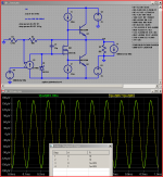
this one uses a modification of the earlier JLH style output simplified amp sim - Fairchild Q model, ~2.2 A Class A bais
the gain is 10x, the .step functions step input vs output V, I sources amplitudes, both at 10 kHz, the load is stepped from 10 Ohms to "infinite"
the plot is the 1 A "output driven" output V green trace vs the diff V between 10 Ohm and "infinite" load for the forward 1 V input, 10x gain which gives 1 A output yellow trace
you can barely see the difference in AC amplitude when I adjust the DC offset to overlay the green and yellow plots
simmed Z_out measured both in "forward" and "output driven" directions is essentially identical in this sim @ 10 kHz (displayed below), and 1 kHz, and 100 kHz as can be verified by editing frequency, .tran args
but sims I can can do
this one uses a modification of the earlier JLH style output simplified amp sim - Fairchild Q model, ~2.2 A Class A bais
the gain is 10x, the .step functions step input vs output V, I sources amplitudes, both at 10 kHz, the load is stepped from 10 Ohms to "infinite"
the plot is the 1 A "output driven" output V green trace vs the diff V between 10 Ohm and "infinite" load for the forward 1 V input, 10x gain which gives 1 A output yellow trace
you can barely see the difference in AC amplitude when I adjust the DC offset to overlay the green and yellow plots
simmed Z_out measured both in "forward" and "output driven" directions is essentially identical in this sim @ 10 kHz (displayed below), and 1 kHz, and 100 kHz as can be verified by editing frequency, .tran args
Attachments
Last edited:
i regularly use the effects of an amp's low output impedance for triaging powered subwoofers and A/V receivers. with a powered sub, it's a simple test to tap on the woofer cone, then turn the power on and keep tapping on the cone. if the sound of the cone deadens and the cone motion gets stiff, the amplifier section is working ok, and the voice coil of the woofer isn't bad.... in receivers, an ohmmeter check across the speaker terminals (power on, no signal) showing near zero tells me the channel is working, and the speaker relay for that channel is engaged.
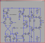
just to see that Class A isn't a special case I repeated the above with my "BobAmp2" circuit using dominant pole compensation - the circuit, Q models are Bob Cordell's - can find discussion in his book thread
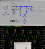
I believe Bob added the stoppers/filtering as examples of parasitic oscillation damping measures
the output Q are slow, biased to 100mA
the sim is for 2.5 A output current, a 4 Ohm Load R, 100kHz is shown
despite the substantial crossover spiking the V(out) delta's fundamentals agree quite well - I also plotted the currents to show that the forward direction phase shift is pretty well explained too
I claim this demonstrates the "small signal, linear" part of the 100 kHz Zout of the BobAmp2 sim has essentially the same value for both the "output injected current" test and the "forward" measurement
(note that even the crossover spike shapes agree to a remarkable extent)
Attachments
Last edited:
here's a link to a schematic of my power boosted Howland current source
AC ohmmeter revisited - Blogs - Electronic Circuits Projects Diagrams Free
AC ohmmeter revisited - Blogs - Electronic Circuits Projects Diagrams Free
- Status
- This old topic is closed. If you want to reopen this topic, contact a moderator using the "Report Post" button.
- Home
- Amplifiers
- Solid State
- Solid State Testing- Tug of war