Hi,
I am thinking of building a guitar amplifier based on the AC30 schematic using parts that I have stripped from an old stereo amplifier. The power transformer that I have is rated 350-0-350 and only has a single 6.3VAC secondary (no 5V for valve rectifier or another 6.3V). The power supply in the original schematic uses a 5AR4 and the B+ is approx 320V. Would this solid state alternative be ok to use? Any advice would be appreciated as I'm pretty new to tubes.
The schematic is here
Attachments
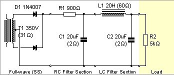
I don't know if that 900 ohm resistor will drop enough voltage (did you calculate it?) but if it does it will have to be rated for about 100 watts dissipation because you are going to be dropping over 100 volts through it. A 350-0-350 transformer puts out too much voltage for the VOX circuit, but you can use it if you don't mind wasting about half of the transformer's power through R1.
Using solid state rectification will alter the sound of the amp; you need to keep a tube rectifier in your amp to keep that "VOX" sound. You can use a couple of 6AU4 or 6AX4 damper tubes for the rectification and still be able to ground the 6.3 volt winding.
Daniel
Using solid state rectification will alter the sound of the amp; you need to keep a tube rectifier in your amp to keep that "VOX" sound. You can use a couple of 6AU4 or 6AX4 damper tubes for the rectification and still be able to ground the 6.3 volt winding.
Daniel
I use Copper Caps from Weber Amps in my Fender Deluxe for years without problems. The advantage is that in any moment you want, you can change it for a real tube rectifier because they use standard tube sockets. And not is expensive.
https://taweber.powweb.com/store/ccapord.htm
https://taweber.powweb.com/store/ccapord.htm
Hmm yeah that power supply works in PSUD2 but real life may be a different story with 100W dissipation across a single resistor. Those copper caps sound like a great idea. Wouldn't actually be able to swap out for a tube rectifier though with no filament connections present but that's not a worry if they're as good as people say they are. I'll do some research and see if they could work.
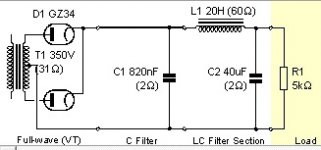
OK it seems that using a copper cap rectifier and a very small first filter cap could work but only if the output transformer B+ connection were connected after the choke. Would this work? Also, would having a small first filter cap increase power supply ripple? My supply now looks like this:
Attachments
Hi Hayden - I don't think your model is realistic at all.
Have you put all the specs for the transformer into the model? If not, you won't get the right result. The 31ohm secondary resistance spec shown in your diagram is the stock setting in PSUDII, so I figure you haven't changed the specs...
Rather than having a fixed resistive load, put a current tap (or two...). Set the current for the idle current of your amp.
The VOX amp has two voltage taps off the B+ - one for the preamp section and the other for the outputs. You need to model this too.
Now you are nearer the mark.
PSUD will show the ripple and the voltages at each point in the circuit. Have a look to find the resultant ripple. Sometimes you have to magnify the resultant waveform to see it. Read the instructions on how to zoom in.
A 350-0-350 tranny with diode rectifiers will give around (Ian runs to the valvewizard site to check) 420V under load. The total load would probably be close to 200mA. You need to lose around 100V, or maybe just 70V if you use JJ EL84 and run a 350V B+. The amp is cathode biased so you'll lose another 10 or 15V there. The 60 ohm choke will drop 60 x 0.2 = 12V. So you need to lose around 45V or 75V for 350V or 320V across the tubes respectively. For 45V drop at 200mA you need 225 ohms and 75V you need 375 ohms. The power dissipated will be 9W and 15W respectively. An aluminium-housed power resistor of twice the rating heatsinked to the side of the chassis with heatsink grease is how I would do it.
The 5K resistor in your PSUD sim will not load your supply correctly. Use Ohm's law. For say 350V and 200mA, you want 1750 ohms load. The valve wizard has good info on power supplies. I wouldn't get real fussed about whether its valve rectified or solid state.
All the dropping resistor calculations so far have assumed a constant load. In actual use, the DC current will vary, so the voltage across a dropping resistor will also vary. This will introduce power supply "sag" - not necessarily a bad thing in a guitar amplifier, but how close it will then be to the performance of an AC30 is debatable. A zener diode string, or "power scaling" could be used for a fixed voltage drop.
A valve rectifier such as the 5AR4 could be used with a separate heater transformer. Jaycar Electronics in New Zealand sell 2 amp multitap transformers. These have a 6-volt tap which could be used, with a suitable dropping resistor, for a 5 volt heater supply.
A valve rectifier such as the 5AR4 could be used with a separate heater transformer. Jaycar Electronics in New Zealand sell 2 amp multitap transformers. These have a 6-volt tap which could be used, with a suitable dropping resistor, for a 5 volt heater supply.
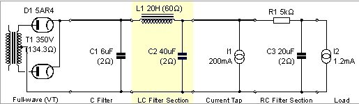
OK this is my improved attempt at a power supply. The 200mA tap is for the quartet of output tubes and the smaller tap is for the preamp section which is meant to be a 290V tap. The B+ tap on the transformer is around 345V in the original schematic (taken before the choke). The B+ in this sim measures 320V but there are a couple of possible problems.
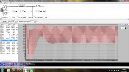
1. The ripple before the choke (tap for output transformer) is huge (around +-200V as shown on graph) because of the small first filter cap. Will this cause problems?
2. There is 6W (30V drop over 150R) dissipated through the resistor before the 290V tap. Is this silly?
1. The ripple before the choke (tap for output transformer) is huge (around +-200V as shown on graph) because of the small first filter cap. Will this cause problems?
2. There is 6W (30V drop over 150R) dissipated through the resistor before the 290V tap. Is this silly?
Attachments
Have you tried getting rid of the first cap? Then you would have a proper choke input PSU, instead of a half-way house. The ripple here is not a problem as long as the capacitor can handle it, so check the capacitor specification.
R1 is not dropping 30V. You have confused peak voltages with averages?
R1 is not dropping 30V. You have confused peak voltages with averages?
Right you are. I accidentally had the current taps set up as stepped loads so their values were changing. I tried designing this as a choke input filter as well but the B+ voltage could not be brought high enough (around 280V max). Here is my power supply at this point. The current through the choke is quite high (550mA max, 220mA at idle).
Attachments
I've dropped some volts with 5-10watt resistors on 1x6v6 and 2xel84 amps but you are facing much more. The tranny you have is 2 strikes against you with the higher voltage and lack of a 5v winding. Diodes means higher voltage. Moving the choke "forward" to feed the output plates means a much higher current capacity spec for the choke. If you are committed to el84 outputs you might consider obtaining an appropriate power tranny. I don't think it would cost too much. Or "VVR" which I haven't jumped into yet.
How are you at solid state electronics? If you have room for an appropriate heat sink, you may want to consider an active voltage regulator using a MAIDA regulator setup with LM317, or something like this http://cgi.ebay.com/ws/eBayISAPI.dll?ViewItem&item=320565567612&ssPageName=STRK:MEWAX:VRI
I wonder what the (increased) cost of a high(er) capacity choke is, compared to the cost of a new power tranny. Taking the B+ off the right side is not the AC30 approach and all 4 el84 plates would then draw all their current thru the choke.
And the mojo gurus would probably say that it wouldn't sound like an AC30 setup that way. You know how particular those guys can be.")
And the mojo gurus would probably say that it wouldn't sound like an AC30 setup that way. You know how particular those guys can be.
Unless I missed something reading the thread....
WHy on earth are you using tiny little 2uf filter caps? And then wondering why there is ripple?
The rectifier tubes have a maximum input filter cap rating, but those can easily be exceeded. And that would be for at least 10x the capacitance. And if you are going to solid state rectification as I believe you said, then those limits don;t apply any longer anyway.
Are you running a sim of the circuit with tube rectifier models? That won't reflect the real world operation with semiconductor diodes. A semi diode will drop maybe a volt, compared with many volts across a rectifier tube.
WHy on earth are you using tiny little 2uf filter caps? And then wondering why there is ripple?
I assume you mean the first filter cap (6uF) which is small in order to bring B+ after the choke down to a sane level. Or you may be looking at the series resistances which are each 2R (the default that the program adds) by mistake. The general idea with this design is to have 3 taps: One at ~345V for the output transformer B+ tap, one at ~320V for the output tube plates and one at ~290V for the preamp plates.
Are you running a sim of the circuit with tube rectifier models? That won't reflect the real world operation with semiconductor diodes. A semi diode will drop maybe a volt, compared with many volts across a rectifier tube.
I am now planning on building this using a copper cap rectifier instead of standard SS diodes. Hopefully this behaves at least a bit like a tube rectifier as it claims to be a drop-in replacement so I'm just using the 5AR4 model from PSUD2.
The rectifier tubes have a maximum input filter cap rating, but those can easily be exceeded. And that would be for at least 10x the capacitance. And if you are going to solid state rectification as I believe you said, then those limits don;t apply any longer anyway.
I guess this would be to reduce the inrush current on startup. I'm assuming this won't apply as much to copper cap rectifiers but the main reason for the small cap is to adjust voltages further down the line (pi filter on input).
- Status
- This old topic is closed. If you want to reopen this topic, contact a moderator using the "Report Post" button.
- Home
- Live Sound
- Instruments and Amps
- Solid state rectifier for AC30 clone