PMA said:As said, you need about 60dB/1kHz for MC. That is approx. 80dB DC (20Hz) gain (total).
I mean, what is a minimum gain we need for first stage.
In order to satisfy the rest of our circuit.
The total gain I am aware of.
MM requires something like +30-50 dB and MC probably another +20-30dB.
The amount is a bit dependent of what you want to feed output into.
To select an output level that can be fed directly to Power Amplifier/Headphone Amplifier
is an attractive approach, to me.
This way we would not introduce any active stage between Phono/Power Amp.
And where is no active gain - is no pain.
Any circuit will add some distortion, more or less.
===========================================
Any added distortion is there forever .. we can never take away once produced.
===========================================
Some people, mostly newbies in audio reason like this:
If I have a less good loudpeaker,
I can compensate this with having an ultralow THD RIAA amplifier
and one very good power amplifier.
It does NOT work this way!
Taking an audio chain of:
CD - Poweramp - Speakers
Say we have these THD figures (1 Watt):
0.001% - 0.050% - 0.500%
The total dist is not
(0.001 + 0.050 + 0.500) /3 = 0.184 %
The end result It will be:
0.001 + 0.05 + 0.5 = 0.551%
Which is THD -45dB.
=========================================
You may argue with me, and say that Good audio speakers
have not such high level of distortion. Not at a few watts ... only.
www.firstwatt.com
There is a speaker brand called von Schweikert. It is among the best speakers in this world. von Schweikert knows his thing.
http://www.vonschweikert.com/
They are not just any speakers, that we 'normal' use. They are a bit more than this.
Soundstage magazine is a serious reviwer of hi-fi loudspeakers.
They actually measure the DISTORTION of test objects.
www.soundstagemagazine.com
May 2003
Von Schweikert Audio VR-1 Loudspeakers: Measurements
http://www.soundstagemagazine.com/measurements/vonschweikert_vr1/
This is the 90 dB SPL results for von Schweikert VR-1.
As sensitivity of this LSP is 87dB, the lower curve shows dist at ~ 2 Watt RMS
An externally hosted image should be here but it was not working when we last tested it.
lineup - friendly hifi regards
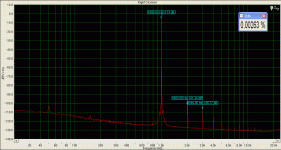
Pavel, what is the nominal THD of your functional generator? Did you use an passive attenuation network between generator and phono input?
EDIT: I would give the first stage the highest gain you can sanily tweak out of a single (plus cascode or current mirror) gain stage.
Rüdiger
EDIT: I would give the first stage the highest gain you can sanily tweak out of a single (plus cascode or current mirror) gain stage.
Rüdiger
I will repeat that meaurement with sharp 1.5kHz lowpass filter, which I use when I want to get rid of generator harmonics. Generator itself has 0.0025 - 0.003%, with dominant 2nd, then decaying 3rd, 4th, 5th .... etc. Very similar to spectrum posted.
It is 7Vrms output, with divider at the output. There was also divider at the input, for the reason of high sensitivity of the MC preamp.
It is 7Vrms output, with divider at the output. There was also divider at the input, for the reason of high sensitivity of the MC preamp.
24 mA had the original but the chosen current determines the signal amplitude from that stage.Lumba Ogir said:peranders,
I am more curious about what the current should be.
You can simulate with good results. Have you done that? If not, download LTSpice for free.

If I may chip in... pardon me...
What about looking (referencing to) a pre-amp design like the old Electrocompaniet Preampliwire II. I used a EC Preampliwire II a few years ago with a MM cartridge and the sound was absolutely amazing. Apparently the circuit operates at +55VDC (= more headroom?)

Dewald
PS - Per Anders' monster MC phonostage looks like a killer - stunning!
What about looking (referencing to) a pre-amp design like the old Electrocompaniet Preampliwire II. I used a EC Preampliwire II a few years ago with a MM cartridge and the sound was absolutely amazing. Apparently the circuit operates at +55VDC (= more headroom?)
Dewald
PS - Per Anders' monster MC phonostage looks like a killer - stunning!
Only for brave peopleGlidingDutchman said:Per Anders' monster MC phonostage looks like a killer - stunning!


Hi Jam,
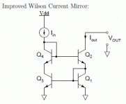
the main reasons are the currents and dissipation involved. With my particular FET's, the Q's source 26mA, which translates into approx. 250mW dissipation in a Widlar. Since the that300 transistor arrays are typical rated to only 20mA it is questionable if i can use them at all, but surely not at 250mW. The Wilson has the added bonus, that the third 'cascode' transistor does not need to be of the same brand/type.
When chosing the right cascode Q (as for example the 2sa1360/2sc3423) one gains additional bandwith and lower thd as a bonus.
Rüdiger
Hi Rudiger,
Thanks for your reply.
What you say makes a lot of sense. I see the advantage of the third transistor not having to be of the same type and reducing the voltage drop across the second transistor. This should reduce imbalance on the mirror due to heat.
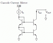
Do you think there will be any advantage to using an enhanced Wilson current mirror or even a cascoded current mirror.
Regards,
Jam
Attachments
Hi Jam,
the answers to your last questions are beyond my experience.
The only thing I can say is, whenever there is a discussion here regarding the sonics of current mirrors it's said that one should keep it as simple as doable or possible for a certain design goal.
Rüdiger
the answers to your last questions are beyond my experience.
The only thing I can say is, whenever there is a discussion here regarding the sonics of current mirrors it's said that one should keep it as simple as doable or possible for a certain design goal.
Rüdiger
PMA said:For the 1st stage, I would suggest something like 20dB gain. It depends on topology used.
Onvinyl said:EDIT: I would give the first stage the highest gain you can sanily tweak out of a single (plus cascode or current mirror) gain stage.
Rüdiger
thanks. yes both replies makes sense.
About current mirrors.
I use currently this type, posted by Jam here:
http://www.diyaudio.com/forums/attachment.php?s=&postid=1522114&stamp=1211926250
Uses 4 Transistors - without cascode
I have found them the most precise, while still not over-complicate things
- Remember:
the more we add into a circuit > the more potential sources of problems/distortions.
This is why Nelson Pass approach, Keep It Simple as possible,
not often fails in deliver good sound with comparably CLEAN Designs.
About cascoding.
Many INPUT stages, with low AC voltage deviation across JFET / Bipolar,
do Not benefit hardly anything from Cascoding.
It is just not worth it!
It is a totally different case, when we have high voltage swing.
Like in VAS Stages or Input Stage of a Buffer-follower.
Here both BJT and JFET can benefit from cascoding.
I have setup circuits where THD was reduced considerably, bya cascode.
And this makes sense
One of the most important feature of CASCODE is to try to keep C-E (D-S) voltage changes to a low level.
Where is not so big delta voltage ( 0-1V signal when we have a supply of 20-25 DC across input pair ),
it is in this aspect not worth the trouble and 'extra addons' to cascode.
Remember, all addons and extras Are Sources of potential Problems.
Where is a device, a rail for current, there is a potential source of distortion.
Where is nothing .. there is also no medium to cause trouble!
There can be other reasons for cascoding. But this you all know.
---
John Curl experience with current mirrors. (see his Dimitri compendium)
He uses frequently emitter resistors to balance the current.
His reason for this, is that he at one point realized
that without these resistors
BJT transistors will deliver more of their own noise along with output current.
In this respect a current mirror can actually be a noise generator

lineup
Hi Lumba,
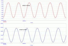
I am enclosing output voltage and current (through eq. circuit) for 20kHz, if it helps. The output current is about 12 mA peak. Yes, the output stage must be capable to handle about 100mA.
The output DC is due to long settling of the circuit that has so high low frequency gain (80dB), but has a low frequency rolloff as well (Hz, 10Hz), a response to suddenly turned on sine. It is neither due to saturation, nor DC servo issue. Only the circuit with bandwidth starting exactly from DC would not do it.
Attachments
PMA said:Only the circuit with bandwidth starting exactly from DC would not do it.
Sorry I was wrong when writing this. It certainly would, as it is a question of transient reponse of the RIAA equalization circuit /even passive/ to suddenly turned on sine.
You sould try LTSpice. You have lots of people here that can help you. Start with something simple like a sinus source, a resistor and a capLumba Ogir said:thank you peranders,
I cannot do simulations properly, I`m afraid, but it`s OK. Many times I instinctively feel that far too low current is provided to drive EQ networks with high capacitances and low impedances.
 If you are able to get a frequency response or may also a step response you can start using active devices like a transistor.
Spice is very pedagogical when you want to explore theories only like a RIAA network perhaps or an active filter.
- Status
- This old topic is closed. If you want to reopen this topic, contact a moderator using the "Report Post" button.
- Home
- Source & Line
- Analogue Source
- Solid state phono preamp design philosophy


