To prove that series diodes are useless?
When they are always open, with low dynamic resistance in respect to the load, and 0.7V drop that is nothing compared to the voltage they supply, you can remove them and listen for yourself.
I used it because one particular pentode went normal with a series diode, what do you say? I don't use any diode in the beginning, just zener. Some units fitted with a particular pentode were returned and so I installed diode as quick fix. That is 10 years ago. I still making them, now about 20 units with me, now all fitted with diode, in case they're use again. The screen dissipation is abnormal (red hot). There is no difference in sound, you're welcome to listen too!
https://www.youtube.com/watch?v=Yqsn7C8x1Xo
Zener diode were fitted because of EL84 parallel output stage that motor boating will occur without it.
Now it appears that over dissipation of particular pentode is that there is some kind of high freq. oscillation, and inserting the diode kills it, that is the best explanation I can think of. That you for your time discussing.. back to OP.
Now it appears that over dissipation of particular pentode is that there is some kind of high freq. oscillation, and inserting the diode kills it, that is the best explanation I can think of. That you for your time discussing.. back to OP.
um... The EL84 is a really superb pentode. I have not had one exhibit high req. oscillation in any circuit I built with them - single ende or PP. Perhaps you were trying screen drive with it? Its quite a poor candidate for that.
Looks to me like a parasitic screen driving, through a poor power supply. It might happen due to some failure in the rectifier that turned to a half-wave instead of full-wave.
No, motor boating is due to unregulated screen supply. 6p14p (not el84 exactly), using zener stabilised the screen voltage. they have independent screen resistor, not sharing. I think partly due some coupling in OP apart through screen supply, the other output stage are not parallel tube, there is no problem even without zener.
Here is the a version of schematic.
Edit: Zener diode apart from stabilization, actually reduce the AC component at screen to a few mV from 5V or so (also confirm by simulation), thereby reduce the cross coupling to minimum and hence eliminate motor boating.
Here is the a version of schematic.
Edit: Zener diode apart from stabilization, actually reduce the AC component at screen to a few mV from 5V or so (also confirm by simulation), thereby reduce the cross coupling to minimum and hence eliminate motor boating.
Attachments

Last edited:
I haven't lost a sweep tube from anything related to the screen.
Fix the screen voltage at 150 to 175 volts WRT the cathode using a regulated supply and you will never blow a screen grid no matter how hard you drive the tube. I use a simple mosfet and zener regulator (no sandophobia here).
It is possible to fix G1 at a low or zero voltage WRT cathode, and drive the screen grid. A rather linear tube capable of pulling it's plate to near zero volts, and idling in the 5 to 10 mA region without crossover distortion will result.
However continuously driving an amp like this to full power or beyond WILL blow the screen grid, and likely cause a G2 to plate tube arc. I have fried enough parts to understand the mechanism, and designed a protection circuit to limit this behavior before the grid begins to glow. It however has nothing to do with this thread.
A simple current limiter is sonically intrusive if the amp is played loud, and as for diodes, some believe that adding a simple 1N4004 in series with the screen will magically enhance the sound....but it only works if you have a Shakti Stone on each transformer to absorb the backwards waves that the diode creates, and some chrome plated unobtanium speaker wire to pass only the good sounds on to the speakers.....don't forget the gold plated power cord!!!!!!
It IS possible to use a zener diode or gas VR tube to drop the G2 voltage a few volts below the plate in triode or UL mode for use with sweep tubes and other tubes with MAX G2 voltage specs significantly less than the plate voltage. This will work up to a point. When the plate voltage gets pulled toward the cathode voltage, G2 will drop to the plate voltage - the zener voltage. When the plate gets near the zener diode voltage the screen will be at zero volts or less, and severe distortion will result. This severely restricts the available undistorted power output.
From a test that I did in 2008:
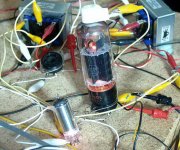
I did some experiments along these lines when I was torturing some sweep tubes at plate voltages that would melt the screen grid. The results were promising but there is only so much to be gained. If you use too big of a zener the G2 voltage can approach zero on low going plate voltage excursions. For those who are sandophobic a gas regulator tube can be used. The photo below shows a 6CD6 with an 0B2 between the UL tap and the screen grid. Do not copy my unique breadboarding method. I think that an 0A2 might have been more suited because when I really cranked it the 0B2 would extinguish on peaks causing some really rude distortion.
Attachments
No, motor boating is due to unregulated screen supply. 6p14p (not el84 exactly), using zener stabilised the screen voltage.
I don't see any Zener stabilized screen grid voltage on your schematic. Contrary, it is Zener - destabilized. Zener in series increases relative voltage change.
I don't see any Zener stabilized screen grid voltage on your schematic. Contrary, it is Zener - destabilized. Zener in series increases relative voltage change.
You mean the screen of the 2 tubes sharing the connection after the Zener could be relatively more voltage change? The idea is that to find the sharing point (of screen voltage) that have little or no cross coupling signal which is causing motor boating. The motor boating does not start until there is an input (output as a result), so there is evident of "interference" or "relative changes" as you put it whatever it is from the same point!
Give me another component that can do the same job!.
Edit: The cathodes are not tied together, any changes here have little or no effect over the other tube.
Last edited:
Which is what I said, and not what you originally said. So my knowledge got me to the explanation quicker than your experience did?Koonw said:Now it appears that over dissipation of particular pentode is that there is some kind of high freq. oscillation, and inserting the diode kills it, that is the best explanation I can think of.
The wonderful thing about circuit theory, which is a branch of electronics, which is a branch of applied physics, which is a branch of genuine science, is that it allows people (and even dumb computers!) to explain and predict the behaviour of circuits they have never seen and never built while those who have merely built circuits without understanding them continue to be puzzled by what happens while their customers suffer from poor reliability.
A zener used as a voltage dropper does not stabilise the screen voltage, it destabilises it - as Wavebourn says. If you want to stabilise the screen voltage you must use the zener as a shunt regulator not a series dropper.using zener stabilised the screen voltage
The only way i see some action of a diode at the sreengrid is when the grid looses more electrons by secondary emission than it recieves.
There where tubes with an electrode beside the screen acting as a cold cathode.The electrons go in like a negative grid current.
An example...(made by Philips)
Mona
There where tubes with an electrode beside the screen acting as a cold cathode.The electrons go in like a negative grid current.
An example...(made by Philips)
Mona
Attachments
 Please try to stay on topic, the OT posts have been removed.
Quote:
using zener stabilised the screen voltage
A zener used as a voltage dropper does not stabilise the screen voltage, it destabilises it - as Wavebourn says. If you want to stabilise the screen voltage you must use the zener as a shunt regulator not a series dropper.
It is the fixed or stable voltage drop across the zener that I speak of, not in the sense of stabilizer in shunt regulator function, the term does apply here.
Start using your terms correctly then.
My solution to parallel output tube screen connection: The fixed drop across the zener allowed feeding to two or more screen grids without motor-boating. The term de-stablised also don't apply, as it's not the same as resistor. The use of shunt regulation here is a lot more complex than necessary, just to do pentode or triode mode at ease. The term screen stabilizing is?
The issue is miss-interpretion of scope, with a few phase is not sufficient not to advise of any valid solution.
Last edited:

Could you elaborate on that a bit more? I've often wondered why data sheets often show shared G2 resistors. In a PP pair wouldn't you get one feeding current into the other on alternate half cycles?In PP it is better to use ONE resistor per BOTH tubes to share the current and drop a voltage.
Last edited:
It's simple really. With PP the current goes up one side and at the same time down the other.Like that the current in a common resistor is more or less constant resulting in a constant screen voltage.Could you elaborate on that a bit more? I've often wondered why data sheets often show shared G2 resistors. In a PP pair wouldn't you get one feeding current into the other on alternate half cycles?
Mona
And how would that affect the dynamics of how the amplifier responds to transients?
Will improve it.
- Status
- This old topic is closed. If you want to reopen this topic, contact a moderator using the "Report Post" button.
- Home
- Amplifiers
- Tubes / Valves
- Solid state current limiters instead of screen resistors