hi
i have a soft start design but i want to make sure that it's connected correctly.
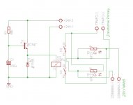
the R1 and C1 are the thermistors delay after the mains has been turned on.
i'm not sure with the connections for the thermistors.
Hope anybody can give some feedback.
Thanks.
i have a soft start design but i want to make sure that it's connected correctly.
the R1 and C1 are the thermistors delay after the mains has been turned on.
i'm not sure with the connections for the thermistors.
Hope anybody can give some feedback.
Thanks.
Attachments
You don't have a timer in the relay driver.
That transistor will gradually turn on over a range of voltage and may not turn on if the 24Vac is a bit low.
Is the relay a 24Vdc type?
Use a 24V or even a 30V regulator to give precision in the delay given by the capacitor.
I don't understand the labeling of the mains connections.
That transistor will gradually turn on over a range of voltage and may not turn on if the 24Vac is a bit low.
Is the relay a 24Vdc type?
Use a 24V or even a 30V regulator to give precision in the delay given by the capacitor.
I don't understand the labeling of the mains connections.
Hmmm... when the relays close it looks like you have them applying a short across the mains and a short across the tranny.
The first relay when closed connects mains 1 and 2 together.
The second connects traffo 1 and 2 together.
I'm guessing you just want it to short out the thermistors after a short delay.
The first relay when closed connects mains 1 and 2 together.
The second connects traffo 1 and 2 together.
I'm guessing you just want it to short out the thermistors after a short delay.
I would say that all you need is one thermistor in the live side to the tranny. Its a series circuit so adding one in L and one in N has no benefit. One set of relay contacts across the thermistor to short it out. The delay need be minimal because the surge occurs at the instant of primary current flowing and is an "unknown" value that depends on the point of the mains cycle that power is applied and the amount of magnetism in the core (which depends on the point in the cycle it was switched off last time in use)
The relay can be driven off a low voltage rail, and in practice I wouldn't be surprised if you did not even need a timer or delay because the rails will take a few 10's milliseconds to come up with the thermistor present. And once they are up the "danger" point is passed. If you found a delay was needed then something like you have but with a small time constant, possibly using an N channel power FET in common source mode.
The relay can be driven off a low voltage rail, and in practice I wouldn't be surprised if you did not even need a timer or delay because the rails will take a few 10's milliseconds to come up with the thermistor present. And once they are up the "danger" point is passed. If you found a delay was needed then something like you have but with a small time constant, possibly using an N channel power FET in common source mode.
Use two transistors.
The switch will run fully saturated when delivering the relay coil current.
The delay transistor must be able to feed that saturated base current, when it detects the changeover voltage. i.e. the delay transistor must pass 2mA for a 20mA relay coil current and that 2mA must flow when all the components have reached their operating voltages.
You don't have a timer in the relay driver.
That transistor will gradually turn on over a range of voltage and may not turn on if the 24Vac is a bit low.
Is the relay a 24Vdc type?
Use a 24V or even a 30V regulator to give precision in the delay given by the capacitor.
I don't understand the labeling of the mains connections.
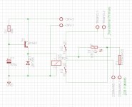
the relay that i have in hand is 12V. the one label that says transformer primary is where the transformer primary is connected. the other label is the 230 V ac mains switch.
Something like this to drive the relay,
http://www.diyaudio.com/forums/solid-state/221014-how-stop-turn-pop-noise-speaker.html#post3191207
http://www.diyaudio.com/forums/solid-state/221014-how-stop-turn-pop-noise-speaker.html#post3191207
Hmmm... when the relays close it looks like you have them applying a short across the mains and a short across the tranny.
The first relay when closed connects mains 1 and 2 together.
The second connects traffo 1 and 2 together.
I'm guessing you just want it to short out the thermistors after a short delay.
there is one relay with two swithces. DPDT.
i want to short out the thermistors after the the mains has turned on.
there is one relay with two swithces. DPDT.
i want to short out the thermistors after the the mains has turned on.
When the contacts close the relay shorts the mains supply.
Attachments
![soft%20start[1].jpg](/community/data/attachments/340/340007-9d448d09e79de720e04fee7905b2bfe6.jpg)
When the contacts close the relay shorts the mains supply.
Do you mean like this Mooly?
Attachments
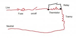
Like this... and this drawings bad even by my standards
woww nice drawing.
so how is the connection now?
Attachments
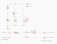
![SS%20V3[1].jpg](/community/data/attachments/340/340226-e4e497000c783b9586cf29c5a6aa2455.jpg)
Like this. The relay contacts can be paralleled to increase current capacity (athough in practice one probably connects/disconnects before the other)
ok thanks. so when the relay switches after a few milli sec, the capacitor stars the charging. Am i right about it? when the C1 is charged, nothing more happens?
Your relay driver works like this...
T1 is biased on via the 68K. That's not ideal because to turn on the transistor, there needs to be enough base current, and as the emitter volts rise so to does the base and consequently there is less and less voltage across the 68K, Less voltage equals less current. The upshot of that is the transistor may not fully turn on and drop some voltage reducing the supply to the relay. That volt drop and current also produce heat in the transistor.
The solution to that is to put the transistor in the earthy end of the chain with the emitter grounded. Now the transistor base can never go more than 0.7 volts positive and so the full supply is available across R1 to turn it on. Its certainly workable but still less than ideal because the cap (now across B and E) would never see more than 0.7 volts and the exponential charging would never really start. Yes it would work but its not good.
The answer to that is to add a series zener to the base so that the transistor only conducts when the voltage on the cap exceeds the zener volts. My preferred solution would be a small FET such as 2N7000.
You're going to want it drawing now I bet
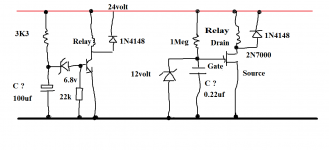
Two versions. Notice the values of the cap and resistor in the FET version. The cap can be a small poly type. The 2N7000 is a great small FET but you could use any power type such as IRF240 etc
i'm a visual person and i understand things more when i see a drawing in front of me.
I tested the first circuit and it worked. how does the 22k resistor help?
I used a power transistor BUX85 and i have found a 24 v relay.
i thought that the delay should be more than 330 ms. because the delay should be 30 s as the recovery time fot the thermistor? or am i wrong?
You sound surprised it worked
The 22k ties references the base to ground. Although it would work without it, its good practice to include it. If the zener is "perfect" then up until the point the zener conducts, the base would be "floating", which is never good practice. If the transistor were a darlington there would be so much gain that even stray "mains hum field" or slight leakage in the zener would turn the transistor on. The value isn't critical as long as it magnitudes more than the 3k3
If a thermistor is really hot it can take ages for it to cool and the resistance to return to the cold value. The whole PCB area is hot too. You have to be realistic. A few 10's of ms or even a 100ms delay won't get the thermistor red hot, the relay shorts it out before that happens. So essentially its running cold and ready to go again after a very short time, and it would have enough resistance to prevent the fuse blowing for another on/off cycle. If you were to sit there switching it on and off then thats a different matter and the thermistor would gradually get hotter and hotter and so less effective.
- Status
- This old topic is closed. If you want to reopen this topic, contact a moderator using the "Report Post" button.
- Home
- Amplifiers
- Power Supplies
- Soft start