The fact that the timing may be three times longer is of no significance, because they have not designed in a reliable timer.
Ok, let's put the NTC in series/parallel point to one side for now.
What's unreliable about the circuit's timer? It seems very able to be modeled, predictable and controllable with a number of variables at the disposal of the user. Mark suggested a hysteresis improvement to ensure the "flick" was assured. What would be your suggestions? I'm sure JojoD may want to hear them should another version be constructed by diyAudio in the future.
The effective resistance of both sets are the same, 40r.
Of course.
The current through both sets are the same
I did say each resistor, not each set.
the heating in both sets are the same.
So I'd take it what you are saying is that I1, I2 and I3 on both figures I attached are the same then?
Keep in mind we are dealing with 50/60Hz. Inductance (due to helical turns) and other impedances are virtually irrelevant to the resistor elements.
Yes we can leave them be.
Attachments
On the subject of an element's current rating (or dissipation rating for that matter), can I ask the following basic and general question: if, for example, an NTC is rated for 2.5A and is on for just half a second, can I integrate the 0.5s wave form and rely on the RMS figure even if that RMS figure were to be much higher should the NTC be on for one full second?
Data sheets are your friend. http://www.mouser.com/ds/2/168/920-325D-LR-245176.pdf
A 2.5A NTC is for steady state.
A 2.5A NTC is for steady state.
Thanks Bob. That was my presumption (and I did have that data sheet sitting on my desk but hadn't flipped it open to confirm my question). I should have used a different example perhaps as it was the general principle I wanted to make sure of (e.g. 'soft-start' resistors only have to dissipate power for a short period).
Perhaps that's a good thing to remember and model. The NTC doesn't need to be operational for the full initial charging of the transformer and smoothing capacitance bank. It will likely be switched out well beforehand and so perhaps the amp and capacitance rating of the NTC may well be enough to get over the hump of that initial charging?
Perhaps that's a good thing to remember and model. The NTC doesn't need to be operational for the full initial charging of the transformer and smoothing capacitance bank. It will likely be switched out well beforehand and so perhaps the amp and capacitance rating of the NTC may well be enough to get over the hump of that initial charging?
I said...........So I'd take it what you are saying is that I1, I2 and I3 on both figures I attached are the same then?...........
You are showing a very different current in the three paralleled resistors.The current through both sets are the same,
I1 left cannot be the same as I1 right.
The left is a part of a series combination of smaller value resistors.
The right is a part of a parallel combination of much larger value resistors.
I1left><I1right.
I said the current is the same.
You are showing a very different current in the three paralleled resistors.
I1 left cannot be the same as I1 right.
The left is a part of a series combination of smaller value resistors.
The right is a part of a parallel combination of much larger value resistors.
I1left><I1right.
I only took that from the net, of course I1 on the left is not equal to I1 on the right. Duh, I guess I should have drawn my own image.
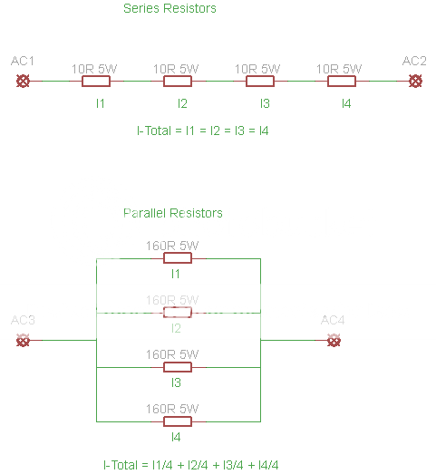
Anyway, what the two images show is that...
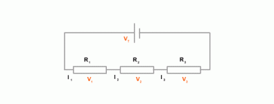
1. The current in series resistors are the same for all resistors.
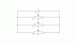
2. The current in parallel resistors are shared by the resistors in parallel.
So to say that 4-series 10R 5W resistors is better than 4-parallel 160R 5W resistors is somewhat reversed? Right?
Is this an indication that the Forum administrators in general will not tolerate any constructive feedback on "your designs".to say that 4-series 10R 5W resistors is better than 4-parallel 160R 5W resistors is somewhat reversed? Right?
Post178 introduced my thinking and my preference
This explains why I suggested to SGK that there may be a better way.I prefer the series connected resistors. The thicker wire of a lower resistance is possibly more robust and should tolerate overload better.
Had he adopted my suggestion based on my thinking that thicker wire might tolerate overload better, and used series connected low value resistances, then it follows that the same arrangement would then suit both fixed resistors, or NTCs.
The FACT that a series arrangement can accommodate either resistors, or NTCs, or a mixture of both, makes the soft start more flexible in that it would suit a wider range of builders, some of whom may prefer NTCs and others who may prefer resistors.
I am pretty sure I have expressed this overload tolerance previously. I wonder where?
Last edited:
Is this an indication that the Forum administrators in general will not tolerate any constructive feedback on "your designs".
First, there's nothing to come clean with. Second, I strongly suggest that you please, please, please, do not mention "administrators" nor moderation to keep this going.
And finally, the reason I joined the discussion is to understand why you want the resistors in series and not in parallel. Besides, I got some time in my hands this week to answer your posts.
Post178 introduced my thinking and my preferenceThis explains why I suggested to SGK that there may be a better way.
Had he adopted my suggestion based on my thinking that thicker wire might tolerate overload better, and used series connected low value resistances, then it follows that the same arrangement would then suit both fixed resistors, or NTCs.
The FACT that a series arrangement can accommodate either resistors, or NTCs, or a mixture of both, makes the soft start more flexible in that it would suit a wider range of builders, some of whom may prefer NTCs and others who may prefer resistors.
I am pretty sure I have expressed this overload tolerance previously. I wonder where?
Would this be enough to explain the current flowing in the resistors? Isn't the current being shared in the parallel arrangement instead of having the same current flowing in each resistor in the series arrangement?

current overload in soft start resistances.
What level of overload can we expect in the soft start resistances.
I'll work through two examples, keeping the arithmetic simple and deliberately avoiding impedance effects.
1.) A 15ohms NTC on a 115Vac supply into a 300VA transformer with a 1ohm primary resistance.
2.) A 100ohms fixed resistor (5off 5W 20r) on 240Vac into a 200VA transformer with 2.5ohms primary resistance.
And assuming a source resistance of 0.3ohms for both cases
1.a) The peak 115Vac voltage is 162.6V
The total circuit resistance is the sum of Rs = 0r3, Pri = 1r0, NTC= 15r, Total = 16r3
The peak instantaneous current can be as high as 162.6/16.3 = 9.97Apk
The permissible peak current for a 15ohms NTC is ? It depends on the rating.
2.a) the peak 240Vac voltage is 339.4V
The total circuit resistance is the sum of Rs = 0r3, Pri = 2r5, Resistor =100r, Total = 102r8
The peak instantaneous current can be as high as 339.4/102.8 = 3.3Apk
The permissible current for a 100ohms 20W resistor is 0.4472Arms
The resistor may have to pass a peak current that is 7.4times the current rating
That is a peak instantaneous power of 54times the continuous power rating.
The instantaneous peak current will generally be lower than as calculated above. These peak current decreases rapidly with time as the transformer flux builds and the transformer "operates".
But even taking account of those assumed reductions, resistors must be switched out very quickly to prevent burning out due to severe overheating.
Last edited:
What level of overload can we expect in the soft start resistances.
I'll work through two examples, keeping the arithmetic simple and deliberately avoiding impedance effects.
1.) A 15ohms NTC on a 115Vac supply into a 300VA transformer with a 1ohm primary resistance.
2.) A 100ohms fixed resistor (5off 5W 20r) on 240Vac into a 200VA transformer with 2.5ohms primary resistance.
And assuming a source resistance of 0.3ohms for both cases
1.a) The peak 115Vac voltage is 162.6V
the total circuit resistance is Rs = 0r3, Pri = 1r0, NTC= 15r, Total = 16r3
The peak instantaneous current can be as high as 162.6/16.3 = 9.97Apk
The permissible peak current for a 15ohms NTC is ? It depends on the rating.
2.a) the peak voltage is 339.4V
The total circuit resistance is Rs = 0r3, Pri = 2r5, Resistor =100r, Total = 102r8
The peak instantaneous current can be as high as 339.4/102.8 = 3.3Apk
The permissible current for a 100ohms 20W resistor is 0.4472Arms
The resistor may have to pass a peak current that is 7.4times the current rating
That is a peak instantaneous power of 54times the continuous power rating.
The instantaneous peak current will generally be lower than as calculated above. These peak current decreases rapidly with time as the transformer flux builds and the transformer "operates".
But even taking account of those assumed reductions resistors must be switched out very quickly to prevent burning out due to severe overheating.
Now you're talking NTCs VS Fixed resistors.
I did not mention............I strongly suggest that you please, please, please, do not mention "administrators" nor moderation to keep this going. ....................
I have already been sin binned for just using the word, irrespective of whether I made a comment on.....moderation
Are you as a Moderator now telling me that I cannot use the phrase "Forum Administrators", or similar, in my posted comments?
I did not mention
Thank you.
I have already been sin binned for just using the word, irrespective of whether I made a comment on.....
Perhaps, but that's in the past and now you are back and shall we work to keep it that way?
Let's make it a healthy technical discussion in the hopes that others (including me) can learn a bit or two from it.
I have always been using either NTCs or Fixed Resistors. It's what interests our Builders.Now you're talking NTCs VS Fixed resistors.
As stated above
A "universal" soft start is more flexible (does that equal "better"?) if it can be built with either resistors, or NTCs.some of whom may prefer NTCs and others who may prefer resistors.
A series arrangement allows that. A paralleled arrangement does not allow NTCs to be substituted for resistors.
I am sure we discussed this series, or parallel, some time in the past.
Are you as a Moderator now telling me that I cannot use the phrase "Forum Administrators", or similar, in my posted comments?
A friendly advice then?
Not sure how this got heated and somewhat personal...
I'd just like to point out that reconstructing the board to take parallel resistors or two series NTC (or just one) would not be hard.
Now let's sort out series resistors versus parallel resistors. The topic was hinted at by Mark as well...
I'd just like to point out that reconstructing the board to take parallel resistors or two series NTC (or just one) would not be hard.
Now let's sort out series resistors versus parallel resistors. The topic was hinted at by Mark as well...
I have always been using either NTCs or Fixed Resistors. It's what interests our Builders.
As stated above
A "universal" soft start is more flexible (does that equal "better"?) if it can be built with either resistors, or NTCs.
I agree, if it can use either NTCs or fixed resistors then it would be more flexible. However, to do that, the resistors also needs to be in a series arrangement.
A series arrangement allows that. A paralleled arrangement does not allow NTCs to be substituted for resistors.
I am sure we discussed this series, or parallel, some time in the past.
However, I'm still confused with the series resistor being better than the parallel resistors in terms of handling current because of current sharing. I do take note about the thicker wire on the lower resistance resistors.
Is there evidence that high value wire wounds can tolerate similar overloads, as can low value wire wounds?
I put enormous short term currents through 10r or 20r 5W resistors, way above the continuous current rating. So far I have not seen unreliablity.
I have done the same with 600mW metal film.
They don't tolerate overload.
Values change, colours change, or they act like a 20second fuse fuming and sparking as they fail.
- Home
- Amplifiers
- Power Supplies
- Soft start circuit design and other psu issues


