Hello everyone!
I am looking for input from more experienced DIYers with this project! Any help is greatly appreciated!
Idea is to have two relays: K1 in series with ICL and K2 to bypass ICL and K1.
Powering ON and powering OFF are two separate sequences.
Power ON:
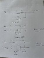
Upon the user operating push button, relay K1 is activated.
After 0.3 seconds (adjustable) relay K2-bypass is activated.
After 1 second, relay K1 is turned off to save on power since now the current is going through K2 only.
Power OFF:
Upon the user operating push button relay K1 is activated.
After 0.3 seconds K2-bypass is disengaged thus directing the current through an ICL.
After 0.7 seconds K1 is disengaged thus completely powering off the device.
I was thinking to create something based only on transistors.
But IC solution will be good too, something with 74hc74 ect.
I am looking for input from more experienced DIYers with this project! Any help is greatly appreciated!
Idea is to have two relays: K1 in series with ICL and K2 to bypass ICL and K1.
Powering ON and powering OFF are two separate sequences.
Power ON:
Upon the user operating push button, relay K1 is activated.
After 0.3 seconds (adjustable) relay K2-bypass is activated.
After 1 second, relay K1 is turned off to save on power since now the current is going through K2 only.
Power OFF:
Upon the user operating push button relay K1 is activated.
After 0.3 seconds K2-bypass is disengaged thus directing the current through an ICL.
After 0.7 seconds K1 is disengaged thus completely powering off the device.
I was thinking to create something based only on transistors.
But IC solution will be good too, something with 74hc74 ect.
Attachments
Last edited:
I recently worked up a similar solution for a job quote that modifies the operation of an access control system-gate operator interface but ~ accomplishes your needs with the exception of re-engaging the ICL on power down. I haven't found that operation necessary but assume you have your reasons. Installation on a customer site means no DIY circuitry which might rob the fun of a design/build but its a solution.
Momentary switch> K1- Impulse relay to switch line voltage ( pulse activated flip-flop with various AC/DC coil variants and 1-2 poles. EX: Finder Relay Inc/ Digikey) with K2 being an adj delay-on-make relay to shunt the ICL after a prescribed period. K2 can be a line voltage coil via the K1 output (single pole) or AC/DC whatever control voltage you use via K1-pole 2.
Cheers
I guess I need to do more research about the problem.
From what I understand, there is a huge inrush current being developed on the transformer and rectifier bridge due to the large capacitors that are not charged and therefore present 0R load upon a startup.
My question now is what about current on turn OFF? Is there a spike at all?
From what I understand, there is a huge inrush current being developed on the transformer and rectifier bridge due to the large capacitors that are not charged and therefore present 0R load upon a startup.
My question now is what about current on turn OFF? Is there a spike at all?
Turn off thump is exhibited by some amps but re-engaging the inrush limiter won't solve that issue. Some people will add a relay to disconnect the speakers just before the amp powers down but I'd rather not imterrupt that path without a real need. Do you have a turn off thump problem? In any case, always turn your power amp on last and off first when using your system.
Good luck, have fun
Good luck, have fun