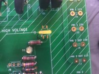
Just such that there is no confusion
v.2.2


v2.3


I can see use cases for both and one doesn't always need additional status information such as can be see on v2.2 nor a momentary switch... but I like that stuff so in light of that, I will stick to v2.2.
Gonna be interesting what is cooking in your brain for v2.4 .. who knows what untapped potential you see
v.2.2
v2.3
I can see use cases for both and one doesn't always need additional status information such as can be see on v2.2 nor a momentary switch... but I like that stuff
Gonna be interesting what is cooking in your brain for v2.4 .. who knows what untapped potential you see
Vunce is correct. These are two different boards (products). Unfortunately, they have similar names and the rev numbers are similar at circa 2.2/2.3.
SFP (soft as a feather pillow) has no remote on/off capability. Just soft start. Latest is 2.3
SFPP (soft as a feather pillow plus) has remote on/off capability plus remote shutdown due to safety trigger. Latest is 2.2.
I am working on an update to SFPP that doesn’t use those pesky SMT flip flop and NANDs with tiny hidden solder pads.
I’m not even close to an expert but I’ll try.
An optocoupler (U2 in your schematic) is an interesting device and highly useful in electronics. I first learned about optocouplers when analyzing the Pass M2 output stage and reading his well written patent.
This application in this softstart circuit however is different.
Two parts are used in an optocoupler: 1) an LED that emits infrared light and 2) a photosensitive device that detects light from the LED. Both parts are contained within the black box with pins for connectivity. The input circuit takes the incoming signal, whether the signal is AC or DC, and uses the signal to turn on the LED. The photosensor is the output circuit that detects the light and depending on the type of output circuit, the output will be AC or DC. Current is first applied to the optocoupler, making the LED emit an infrared light proportional to the current going through the device. When the light hits the photosensor a current is conducted, and it is switched on. When the current flowing through the LED is interrupted, the IR beam is cut-off, causing the photosensor to stop conducting.
There are many applications for optocouplers but I don’t want to bore you. In this application, it appears to be a mosfet gate driver (Q1 and Q2 in the schematic) , and essentially we are using small digital voltages to control large AC signals (i.e. as a mains soft start to control the 120V mains voltage).
I’m sure the designer @jhofland can expand even more and teach us.
Best,
Anand.
Last edited:
- Home
- Group Buys
- Soft as a Feather Pillow (SFP) SSR Soft Start Circuit GB
