I want to try SMPS with Class-A amp. Are there any SMPS module with +/-18V main output with at least 4Amp? I found a few options for +/-24V and above.
I use 19v laptop bricks, for class A it works very well. No noise issues whatsoever. Overcurrent protection standard. You will find one rated 4 or 5 amps easily. Also good for the planet and your wallet to reuse them.
not so wise old tech")
++1
You can't buy a new electronic device/gadget that has anything but SMPS power supply, except if it is some alleged good quality audio product. We are surrounded with SMPS power supplies in our home or at work.
I believe it is right time for some shift in area of power supplies for power amplifiers. Pass Labs is usually leading the way by example. Esoteric VFET power amp powered by evil SMPS!!
There are ACA and MoFo examples as well. Mark Johnson made a very good after SMPS filter design and is working on next version.
I used to think otherwise, but I'm very impressed with contemporary SMPS supplies, even with the cheap Chinese ones.
My opinion is that right direction is not to open new niche of dedicated SMPS supplies for audio, with lot of “snake oil” potential, but to use good quality and cheap, available in all “colors”, SMPS supplies with good universal after regulator or passive filter. Thanks to Mark, filters are available.
As for the regulator, I’m entertaining myself for some time with super regulator that works from 10 – 60 V and can supply 10 A current with 0.5 V dropout, 5 A with 0.25 V dropout. Measured PSRR is over 120 dB at 100/120 Hz and regulator noise is about 2 uV total. Using combination of passive filter + super regulator, expected PSRR @ 100 kHz is about 100 dB. Measured output impedance in the audio band is about 0.25 mΩ. Load and voltage regulation are very good too. I.e. 4 A load change drops output by 1 mV. For one rail, dimensions are 60 x 90 mm including heatsink, so this should fit in the existing designs.
In short, this regulator is a solution for my future builds that helps me avoid: expensive audio grade transformers, fast diodes and fiddling with snubbers, massive (expensive) capacitor banks and chokes, dual mono supplies ….
If there are others that think this would be useful for their past or future builds, I’m willing to provide proper documentation including gerbers, BOM, build guide and help. I’m about to place an order for next test revision boards, so this could be ready in two months.
not so wise old tech
Benchmark has been using SMPS for years in their highly regarded products.
Can't say it better myself, wise in old tech, probably not so much otherwise.
Oh please, give me a break already.
Would it be possible to use two of these in parallel for a higher output current?1. Has anybody cascaded a number "N" of thess filters (N>1) in a daisy chain, to get even greater filtration? Yes. They report the sonic result IS perceptable and IS improved, but only slightly. Diminishing returns even at N=2.
2. Do I have any plans to experiment with higher current filters, suitable to 30WRMS per channel, Class A power amps? Plans, yes. Success is not guaranteed and completion date is unknown. Neither one of us knows; not you, not me.
_
There are ACA and MoFo examples as well. Mark Johnson made a very good after SMPS filter design and is working on next version.
I used to think otherwise, but I'm very impressed with contemporary SMPS supplies, even with the cheap Chinese ones.
My opinion is that right direction is not to open new niche of dedicated SMPS supplies for audio, with lot of “snake oil” potential, but to use good quality and cheap, available in all “colors”, SMPS supplies with good universal after regulator or passive filter. Thanks to Mark, filters are available.
I think there's some 'education' needed just so buying a cheap Chinese SMPS is less likely to end up in failure. Unfortunately design and components cost money, so there's cheap and then there's cheap.. not all cheap SMPS are built with safety in mind (thinking headphones).
Also given a nice 100-200kHz supply will end up being less efficient due to switching losses and the need for more design, it's likely to be better for audio.
However if you have a BFOF (big FO filter) that does the job with the most arcane SMPS bashing away in the audio spectrum.. thumbs up
I still have a hankering for getting a 100-200kHz switcher working from PFC to output.. with + & - 320V rails, along with heaters etc.. that would be a real alternative to linear for most.
It might be a little tight for certain amps, this power supply is rated with a max of 1.5A per rail.
The 3A rating is actually the total from the positive AND negative rails.
Would be good for 8 ohm load. Haven’t tried this one but his product are normally noise free.
BR
Eric
Last edited:
In my own opinion, SMPS supplies have no business in a good audio amplifier.
These noisy, touchy, often cheaply made buggers will never go into an amp that I'd build.
Sorry, I'm Old School, and a nice qualified power transformer owns its place pushing a well designed power supply.
Since amplifiers were built, why do you think they always had a transformer?
I mean no disrespect!
But with this attitude we would still be debating whether VHS is better than Beta...
Or whether digital photography has a chance against film.
Recently added Vfet to the list of classA amps running on smps.
Absolutely quiet, sweet sounding amp.
However if you have a BFOF (big FO filter) that does the job with the most arcane SMPS bashing away in the audio spectrum.. thumbs up
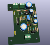
No, it’s an op amp based super regulator and offspring of another regulator on attached picture. This one was intended as add-on module that replaces resistor in CRC supply. Works well but I don’t like what happens to the MOSFET when used with say, 600 VA per rail transformer, no soft start, and HUGE capacitor bank at the regulator output. Smells funny.
Adding current limiter is not a problem but then it won’t be good for diy as current sense IC is only 2 x 2 mm.
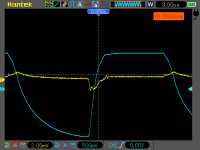
Anyway, this same regulator is expanded with additional HF passive filter at input and small decoupling capacitors. Attached is measured transient response of that variant, at 30 V output and current change from 1 A to 9.2 A. Blue trace is voltage at 0.33 Ω current sense resistor. Base 1 A load is not visible there. Rise time of roughly 10 µs corresponds to fastest audio signal, so I think transient response is good.
Current module 3D outline is attached as well. I don’t have 3 D model for the used heatsink, so it is not visible on render.
Attachments
In my own opinion, SMPS supplies have no business in a good audio amplifier.
A "good" audio amplifier will have very high PSRR and will have no problems dealing with any power supply noise that presents itself in the audio band. Have you ever put a CRO on the power supply rails of an amplifier playing music? If you do you will notice that your transformer and large filter caps really aren't that good at keeping your supply rails clean. I see less ripple under a dynamic load using a quality SMPS than I ever did with unregulated linear supplies.
Not nice, you are underestimating him with CRO (cathode ray oscilloscope). Being old but wise, he has upgraded to digital sampling oscilloscope that makes him able to measure one single nanovolt signal levels. 
https://www.diyaudio.com/forums/power-supplies/359652-fine-ic-voltage-regulators-12.html#post6334547
Sorry wiseoldtech, I had to dig this out as it was an epic blunder and, apart from technical discussion, we are here for the entertainment as well.
https://www.diyaudio.com/forums/power-supplies/359652-fine-ic-voltage-regulators-12.html#post6334547
Sorry wiseoldtech, I had to dig this out as it was an epic blunder and, apart from technical discussion, we are here for the entertainment as well.
wiseoldtech
Experience tends to trump enthusiasm, and for me they always oscillate until a happy medium is reached. Both ways are just valid, both ways have pros/cons and supporters. I would quite happily pick peoples brains over a glass, although I know my slightly hyper style can grate. My point here is I may poke fun but I welcome any comment - both positive or otherwise
There's fun in being stubborn
The CUK topology is great for step up and smaller changes of voltages, but for large drops it needs better current handling or the mosfet burns a lot (even with a expensive mosfet). I'm thinking of coupling a resonant tank/phase (ie multiple mosfet) buck then running that to reduce the current problem for the initial drop then if need be add a secondary step-down (even a maida regulator may work to remove noise/step down further).
The Cuk's main issue is the current through the mosfet.. and that quickly can end up with very high voltage spikes.
Hmmm ...
The Cuk's main issue is the current through the mosfet.. and that quickly can end up with very high voltage spikes.
Hmmm ...
Since amplifiers were built, why do you think they always had a transformer?
The obvious reason.....when the first amplifiers were built, mosfets, BJT's and most of the parts found in a modern SMPS were not yet invented.
Bust open any isolated SMPS (anything used in this forum) and you will STILL find a power transformer. It just looks a bit different now.
As with amp design itself, it is possible to make a good clean SMPS, and it's possible to make a cheap and dirty piece of crap. The choice is up to the designer, and the constraints he is subject to at design time. Budget and size being the biggies here.
Just because a given SMPS presents a very low noise on its output, doesn't make it suitable for use in an audio amp, or anything near an audio amp, shortwave radio, or other device sensitive to electromagnetic interference.
Regulatory agencies in most countries have specs as to the interference pushed back into the power lines or present at any user accessible terminal (conducted spurious emissions), and directly radiated from the device (radiated spurious emission). Most of the cheap devices found on Ebay, Amazon or other sites do NOT pass a proper certification test, if they were ever tested at all. Neither do many LED light bulbs.
I'm still wrestling with the idea of building a 1 KW vacuum tube audio amp before I get too old to physically move it. At my current age SMPS will be required, a pair of big A$$ OPT's and suitable chassis are heavy enough. Now where to I get 625 volts at 3 amps? Maybe 13 of these in series?
Blocked
Not nice, you are underestimating him with CRO (cathode ray oscilloscope). Being old but wise, he has upgraded to digital sampling oscilloscope that makes him able to measure one single nanovolt signal levels.
https://www.diyaudio.com/forums/power-supplies/359652-fine-ic-voltage-regulators-12.html#post6334547
Sorry wiseoldtech, I had to dig this out as it was an epic blunder and, apart from technical discussion, we are here for the entertainment as well.
Make all the fun you want, it's typical of online chatter blogs anyway, and I'm quite immune to it.
In comparison, the behavior of others in my profession, as well as novices, during "in person" discussions never seems to have any of the traits that "onliners" seem to feed upon.
I attribute that fact to the obvious lack of really knowing who's on the other end of your screen, and what their experience and qualifications are, as well as the anonymity factor..
For all I know, it just might be some 14 year old self-proclaimed expert enjoying a bit of "trolling" or baiting.
What you don't seem to know about is that I still have a "CRO" at my workbench for specific measuring and analizing purposes, along with several custom made pieces of equipment geared towards what I do.
But discussing that is not really important.
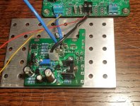
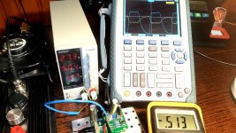
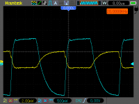
I understand that numbers I’ve mentioned (60 V, 10 A, > 120 dB PSRR, 2 uV noise) may look, ahem … “optimistic” for such a puny looking regulator, but they all are proper measured. As a little backup for those numbers, here is a “live” picture of measurement session where previous regulator iteration is “upgraded” with onboard decoupling caps and Murata input filter. It is loaded with 7.9 A @ 20 kHz with 4 us rise time and 1 A constant base load. For a such load, you would need amplifier with 80 kHz power bandwidth. I’m using active load driven by signal generator.
Multimeter displays dropout voltage of 513 mV and SMPS lab supply is putting out 5 A on average. Yellow trace is regulator output. It is visible that dynamic voltage drop is exactly 3 mV which determines output impedance @ 20 kHz as 0.38 mΩ. Oscilloscope screenshot is attached.
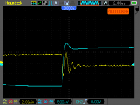
Another one is 20 kHz load with 400 ns rise time. For that you would need an amplifier with 800 kHz power bandwidth. There is visible actual regulator speed limit. It reacts in 250 ns time.
I think that transient response is among critical properties of regulator intended for audio use if amplifier modulates power supply while providing AC current at output. Single ended designs having CCS in the output stage are exempt of this requirement.
If anyone wonders where is that op amp I claim that regulator is based on, I remind you that every PCB has two sides. It’s down under.
Multimeter displays dropout voltage of 513 mV and SMPS lab supply is putting out 5 A on average. Yellow trace is regulator output. It is visible that dynamic voltage drop is exactly 3 mV which determines output impedance @ 20 kHz as 0.38 mΩ. Oscilloscope screenshot is attached.
Another one is 20 kHz load with 400 ns rise time. For that you would need an amplifier with 800 kHz power bandwidth. There is visible actual regulator speed limit. It reacts in 250 ns time.
I think that transient response is among critical properties of regulator intended for audio use if amplifier modulates power supply while providing AC current at output. Single ended designs having CCS in the output stage are exempt of this requirement.
If anyone wonders where is that op amp I claim that regulator is based on, I remind you that every PCB has two sides. It’s down under.
Attachments
Make all the fun you want, it's typical of online chatter blogs anyway, and I'm quite immune to it.
In comparison, the behavior of others in my profession, as well as novices, during "in person" discussions never seems to have any of the traits that "onliners" seem to feed upon.
I attribute that fact to the obvious lack of really knowing who's on the other end of your screen, and what their experience and qualifications are, as well as the anonymity factor..
For all I know, it just might be some 14 year old self-proclaimed expert enjoying a bit of "trolling" or baiting.
What you don't seem to know about is that I still have a "CRO" at my workbench for specific measuring and analizing purposes, along with several custom made pieces of equipment geared towards what I do.
But discussing that is not really important.
Whoever proclaims himself to be a wise old techie, guru and what not and then occasionally posts some hilarious opinions, must endure some flack.
Thank you for making this forum more cheerful place.

On the CRO matter, yeah, I would like to still have my first CRO as they are better for some measurements, not having 8 bit vertical resolution limit.
@tubelab_com that looks and interesting project 600+V and 1KW looks more like interleaving or full bridge. Oddly there seems to be more 1-4kW supply designs out there so it may be easier than you think.
TI have a 1.2kW ref design and I’ve seen 4kW supplies too as reference designs.
A x kW pfc will get you to 390V typically, then it’s really just adding after. Only issue is the smell of expensive switches going pop ��
TI have a 1.2kW ref design and I’ve seen 4kW supplies too as reference designs.
A x kW pfc will get you to 390V typically, then it’s really just adding after. Only issue is the smell of expensive switches going pop ��
Whoever proclaims himself to be a wise old techie, guru and what not and then occasionally posts some hilarious opinions, must endure some flack.
Thank you for making this forum more cheerful place.
That's all well and good tombo...
The occasional "flack" as you call it is not a big deal, because I basically brush it off as internet blabber anyway, compared to the tens of thousands of real people, my customers through the decades, that have given me high marks for my work.
- Home
- Amplifiers
- Power Supplies
- SMPS for Hi-Fi?