Now I am busy with Bi-amp with LM1876. I build LM1876 as per datasheet's page # 2 Typical Application circuit. Changes are.
1) Added Output resistor with inductor i.e. 10R resistor wound with 0.5mm enamelled copper wire.
2) Ci cap for Tweeter Amp used 1uf.
3) Ci cap for Woofer Amp used 100uf.
4) Gain resister used 4.7k/100r
Observations :
1) Output resistor with inductor running very hot. And after 2 min. it smoked. (copper wire burned)
2) I skipped output resistor then I found Diode at power supply running hot.
3) I replace 1uf with 100uf at tweeter side amp then Amp was stable. But I damaged cheap tweeter.
0.5mm dia looks quite thin. it should be atleast 1mm thick.
yes, i will try.
whats the wattage of output resistor,
1 Watt.
whats the condition of zobal resistor..
No zobel.
Ci cap is no problem.
First put a zobal network of 2.2 ohm, 2W and 0.1uf cap. If it also get burn, this means there are high freq stray vibrations across the feedback loop. put 200nf cap between +- signal inputs of IC and also try to use the special application amplifier circuit as proposed by NS in LM4780 datasheet.
First put a zobal network of 2.2 ohm, 2W and 0.1uf cap. If it also get burn, this means there are high freq stray vibrations across the feedback loop. put 200nf cap between +- signal inputs of IC and also try to use the special application amplifier circuit as proposed by NS in LM4780 datasheet.
put 200nf cap between +- signal inputs of IC
Is this 200nf or 200pf
I just finished the Auxiliary Amplifier Application
Circuit on page 6 - it seemed a more complete setup than the one on 2nd page.
Changed:
- Cin from 1uF to 3.3uF
- Ci from 10uF to 22uF
- Rf from 20k to 47k
The amp runs well, no signs of overheating components, it has been running at almost full blast for 3-4 hours several times. Supplies are +/-20V.
Output inductor is 10 turns of some 0,8-1mm copper wire around 1W resistor.
I wonder what could be wrong with your application. Do you use an input capacitor? Perhaps some DC has made it's way in.
Maybe you should not use such low values for gain resistors. My amp works with 47k/1k, I have not tried 4.7k/100R.
Hopefully you get it working, it's a nice chip!
Supplies are +/-20V
Is that DC ? or AC
Do you use an input capacitor?
No, No input cap used. but I will use it no problem.
Maybe you should not use such low values for gain resistors.
Yes, I should immediately replace to 47k/1k
tuhkam : I still fighting for MUTE/STAND-BY. How do you manage it ?
Thank you for your reply
Best Regards.
+/-20V is DC, after it has passed the rectifier and filter.
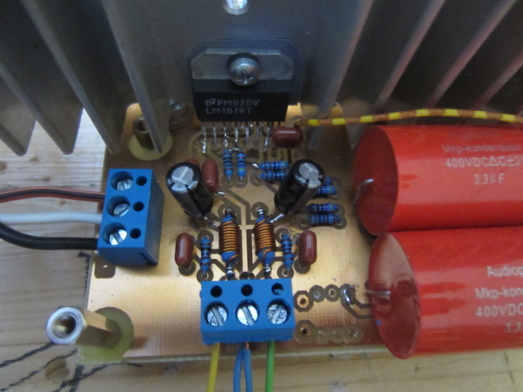
I'm still having problems with the mute (I left the standby pins floating). I connected both mutes together on the PCB and routed them to a pad where I can now supply voltage from outside the PCB.
I used 2V, but it didn't work. I will try it with 5V next. The datasheet mentions a "logic high", but a graph there suggests it should mute with a couple of V already.
A pic of the thing! The yellow/brown wire is where the mutes come together.
The empty holes on the lower edge are summed mono line output for sub.
Thank you for posting picture which is very clear and informative. About MUTE/STAND-BY same story with me. I have also connected MUTE/STAND-BY together for both amps and left floating.
@tuhkam : I am looking for the solution, you are requested, if you got it. please post.
Thank you tuhkam
Best Regards.
@tuhkam : I am looking for the solution, you are requested, if you got it. please post.
Thank you tuhkam
Best Regards.
I suggest that you both move the four decoupling capacitors to be as close as possible to the power pins. The inductance of more than a few centimeters round trip will begin to degrade the transient response and will also contribute to tendency toward instability.
----------
It's on the order of 180-220 pF or so (not nF).
----------
put 200nf cap between +- signal inputs of IC
Is this 200nf or 200pf
It's on the order of 180-220 pF or so (not nF).
It looks like 2.5V should *always* trigger mute and standby according to the datasheet.
Means 2.5v Positive to mute/standby pin would enable mute/standby. means Amp would calm.
Is this correct ?
I suggest that you both move the four decoupling capacitors to be as close as possible to the power pins. The inductance of more than a few centimeters round trip will begin to degrade the transient response and will also contribute to tendency toward instability.
----------
It's on the order of 180-220 pF or so (not nF).
Thanks gootee for pointing that out!
This IC has three supply pins, therefore using three 100n caps. Those are the two on the right and one on the left of the IC.
The VCC A and B caps are about 2,5 and 4 cm from the pins, the one for VEE is 0,5cm.
I noticed that one channel pops a little when turning off power and the other one almost doesn't. I will try using small ceramics on bottom side of PCB and go for equal distance next time.
I wonder how do manufacturers manage to make the pinout always so difficult to work with. Maybe trying to reduce crosstalk and other bad things by mixing the pins
I would love to have the in, out, power, logic pins grouped side by side.
The PSU has 4x4700uF and a snubber. The caps are some generic 35V variety.
The 100nF decoupling and zobel caps (brownish red) are Panasonic polyester ones from ebay like these
Panasonic's Polyester capacitor 0.1uf/63v 120pcs | eBay
Not the best source, but they were cheap.
I have also used these in the past, they seemed even better. Maybe even a waste for decoupling, many people recommend ceramics close to a chip.
Panasonic SMF 0,1uF :: Stacked Metal Film :: Panasonic :: Film / Foil :: Capacitors :: Passive Components :: Electronic Parts :: Banzai Music
The 22uF electrolytics on the amplifier board are
Panasonic NHG 22uF 100V :: Panasonic NHG :: Panasonic :: Electrolytics :: Capacitors :: Passive Components :: Electronic Parts :: Banzai Music
Thanks gootee for pointing that out!
This IC has three supply pins, therefore using three 100n caps. Those are the two on the right and one on the left of the IC.
The VCC A and B caps are about 2,5 and 4 cm from the pins, the one for VEE is 0,5cm.
I noticed that one channel pops a little when turning off power and the other one almost doesn't. I will try using small ceramics on bottom side of PCB and go for equal distance next time.
I wonder how do manufacturers manage to make the pinout always so difficult to work with. Maybe trying to reduce crosstalk and other bad things by mixing the pins
I would love to have the in, out, power, logic pins grouped side by side.
I totally agree about the inconvenience of some chips' pinouts!
For a 100 nF decoupling cap, the total round-trip connection length should be a couple of millimeters or less. They have to be able to work well at up to tens of MHz or more, to prevent high-frequency instability. So any "centimeters" will make the inductance of the connections way too high. Maybe try surface-mount parts, or small multilayer X7R ceramics, on the bottom of the board.
You must also have an electrolytic for each of those (in parallel), with a maximum of probably two or three centimeters total connection length for each one, but much less if AT ALL possible. (By the way, the electrolytics are the ones for which you might have to calculate the minimum value needed in order to handle the worst-case transient current demand.)
The power and ground rails will probably have to be routed with the minimization of the decoupling caps' connection lengths in mind. But even then, sometimes the decoupling caps will need to be soldered directly to the chip pins. But in that case make sure that you temporarily heatsink the pin that's being soldered! You can put some rubber bands on the handles of your long-nosed pliers and clamp them to the pin, _between_ the device and where you're going to solder. But still, don't overheat the pin!
P.S. Film caps "can" work well, for decoupling. But they can also easily cause serious trouble (or even subtle degradations, which you might never track down, or even realize) because their ESR is so low that their capacitance will form high-frequency resonances with the always-present stray inductances. Unless you have a good oscilloscope or RF spectrum analyzer, it is almost always wiser to use a plain electrolytic in parallel with a small X7R multilayer ceramic, with absolute-minimum connection lengths
P.P.S. By "snubber", I hope that you meant a resistor, with an optional series capacitor, and not just a capacitor (which is not a snubber at all, except possibly if it has a rather large ESR).
For example, a small-value film cap placed in parallel with a large electrolytic cap in the filter section of a power supply is a particularly bad idea (and useless, as well). It might not do much harm if a small-value resistor is placed in series with the film cap. That makes an actual snubber. But you'd need a scope to see if you even needed a snubber (to damp high-frequency ringing or resonance), and to pick the optimal value for the resistor (and the cap). Chances are that you wouldn't need a snubber at your PSU filter caps, although they are sometimes needed across the rectifier diodes.
The capacitor is always optional in a snubber, and is ONLY used so that only the "unwanted" higher frequencies can "see" the resistor, if its power dissipation would be too high otherwise.
If you really want a film cap in parallel with a large electrolytic in a PSU, use one that is AT LEAST one percent of the electrolytic's value. For a 4700uF electrolytic, that would be a minimum of 47uF film. Those can be large but maybe only twice the diameter and twice the higth of the electrolytic, and can be purchased for $10 each or much less. Unfortunately, they usually have axial leads.
Sorry if some of that sounds too "preachy". Just trying to impart what I consider to be some important information.
- Status
- This old topic is closed. If you want to reopen this topic, contact a moderator using the "Report Post" button.
- Home
- Amplifiers
- Chip Amps
- Smoke at LM1876's output resistor having inductor