If you use
(t^2+x^2)^1/2 up to where x=15
after this use
19+(-x^2-12.42x-664.1)^1/2
(all in mm.)
to the mouth, and driven by a flat 25mm. piston you get this sonogram
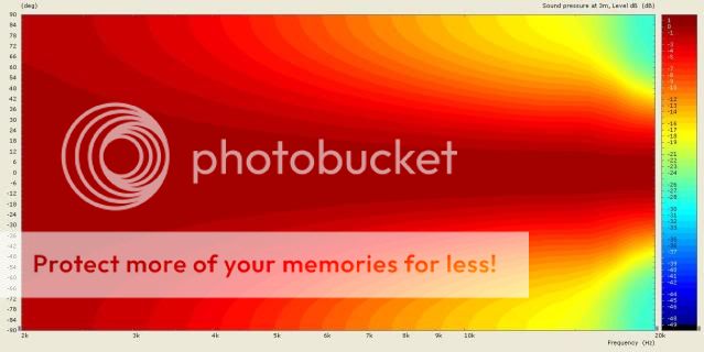
The mouth at 76mm. is about as big as you can use for a 3kHz. crossover and still get a decent vertical pattern with a five-five and a half inch driver.
rcw.
Which application did you use to make the sonogram? Thank you.
Since you will be EQing, I assume, then don't even worry about "loading", it doesn't matter.
Ok, how about directivity controll?
Placing something in the mouth of a good horn can do all kinds of bad things.
You mean throat? 😱
The DE10 is not my favorite driver, I stepped up to the DE12 because it works a lot better.
Because of the possibility to cross lower? Or is it other factors that makes it easier to "work" with? 🙂
Ok, how about directivity controll?
You mean throat? 😱
Because of the possibility to cross lower? Or is it other factors that makes it easier to "work" with? 🙂
Directivity control is dominated by the mouth radius and the wall angles. Smaller angle with larger mouths work best, while wide angles with small mouths are basically not doing much of anything. Everything in between is proportional.
You said that you wanted to mouth the DE10 coaxially with a larger horn. This places it in the mouth doesn't it? How can it be in the throat? Unless the throat is very large.
The DE12 is a real compression driver, but the DE10 is a 1 inch diaphragm feeding a 1 inch throat. Its basically not a compression driver, just a direct radiating tweeter. The DE10 matches a waveguide better, I presume because of a more coherent wavefront.
Thanks for the reply. The plan was to place it just above the throat of the larger horn, and enclose it in an spherical ball to avoid some of the worst reflections.
Ive come up with another combo that might be something. BMS 4555 coupled to the JBL 2352 from 500-6000 hz, and then the B&C DE35 above that.
Whaddaya think?

I don't get too deep into specific design details, but why not just mount the two horns in the same baffle? Then you don't need a spherical enclosure.
I don't get too deep into specific design details, but why not just mount the two horns in the same baffle? Then you don't need a spherical enclosure.
That would be the plan yeah. 🙂 And the JBL 2226's under that again. Im unsure if the BMS really can reach 500hz though... What happens if one uses a driver below the horn cutoff?
That would be the plan yeah. 🙂 And the JBL 2226's under that again. Im unsure if the BMS really can reach 500hz though... What happens if one uses a driver below the horn cutoff?
Personally I don't buy the whole "horn cutoff" thing, so as far as I am concerned nothing bad happens. In fact I do it all the time (depending on what you define as "horn cutoff").
Here is a coaxial sceme I modelled on Axidriver..
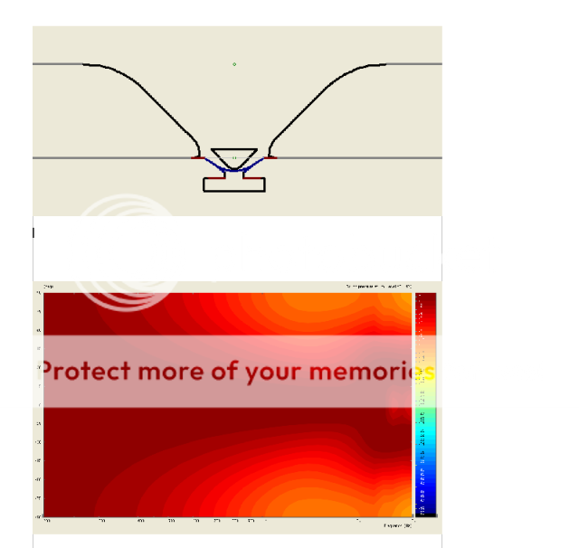
As you can see at the upper end it starts to develop a center minimum, indicating the wavefront is a good approximation to spherical.
rcw.
As you can see at the upper end it starts to develop a center minimum, indicating the wavefront is a good approximation to spherical.
rcw.
... indicating the wavefront is a good approximation to spherical.
rcw.
They are other things that can cause a response like this. The large flare in the polar response would indicate to me that there is significant shadowing from the device in the throat and that sound is bouncing off the side walls. I would contend that the wavefront is most decidedly NOT spherical.
If you use a smaller mouth and use a relatively larger amount of mouth flare you get this..
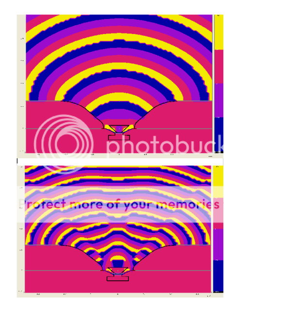
The wavefront is good up to where the wavelength is around twice the obstacle dimension, after this it starts to get ordinary, but a 2.5kHz. crossover is o.k.
rcw.
The wavefront is good up to where the wavelength is around twice the obstacle dimension, after this it starts to get ordinary, but a 2.5kHz. crossover is o.k.
rcw.
How critical is it to use a 1,5" driver for the JBL horn? Can a 1,4" driver be used, or will that give an uneven freq response?
How critical is it to use a 1,5" driver for the JBL horn? Can a 1,4" driver be used, or will that give an uneven freq response?
Matching the driver to the waveguide throat is pretty important.
Matching the driver to the waveguide throat is pretty important.
Even with the horn throat just 1 mm too big? 37 mm vs. 39 mm.
Even with the horn throat just 1 mm too big? 37 mm vs. 39 mm.
I can only give you my experince with my own waveguides. 1 mm difference in radius is very large and I try to acheive .1 mm in diameter matching - which is very difficult. A mismatch at this point causes the wavefront trip "trip" at a critical point in its propagation. You won't see this problem in most designs because the waveguides are not good enough to maintain a coherent wavefront anyways, but in a good waveguide it is readily measureable.
- Status
- Not open for further replies.
- Home
- Loudspeakers
- Multi-Way
- Small waveguide for B&C DE10 - diy?