bjorno, I think I now understand the size and shape you are suggesting. It looks very doable (even with my limited woodworking ability).
I've been reading some on TL speaker design and one thing I run into is often (?) the box is stuffed with insulation (which is contrary to the "standard" reflex sub box design which just lines the walls with insulation). Other times, it seems not to be and then on some projects, they say to try out stuffing to see where the "sweet spot" is. So do I stuff the "tube" part, the part where the speakers are, both, or neither? Or do I experiment with stuffing to do the final tuning? I can use dowel rods or my original braces to keep the insulation from settling in the box.
Note that I will be going "dark" for the next week as I travel to Helsinki for a meeting with a bunch of European meteorologists. It doesn't mean I've abandoned the project, I am just not going to be able to update while sitting in my hotel room (or playing tourist around Finland).
Thank you very much for the added information.
I made the first step by duplicating your results. That's a good sign I at least am running Hornresp the right way.If you want to use more than one driver the the CSA:s S1,S2,S3,S4 and S5 must be enlarged correspondingly e.g.:
If 3 drivers then S1...S5 should be multiplied with 3 to get the correct areas bu the section lengths L12...L45 should alwauys remain the same.
Now it doesn't seem like either of the Hornresp outputs you show match the dimensions in the speaker diagram in the upper left hand corner. That's too bad as that design would really work well.
Since I will be driving each speaker with a separate channel of the amplifier, why can't I just increase the Sd parameter by a factor of 3, since all three of the speakers will be working the same way? I know that gives some odd results, but I can tune things to fix it (I think, I've not actually tried it yet).
Those look nice, but they are at least 2X the cost of the TB drivers. Not sure if I can swing that. Also the frequency response seems to be NOT as good on the low end (but I may be reading it incorrectly).You might want to have a look at the Exodus EX-Anarchy 6.5" driver it's definetly mechanically quieter and also IMHO more musical oriented(lower distortion) than the similar TB drivers.
There are almost 700 responses in that thread, and the pictures seem to be broken. So I don't know how big they are or where to get more information about getting the flat packs. Any suggestions would be helpful (and appreciated).Also while your at it you might want to really consider an alternative design, say something like building 2 of these proven, tested and measured LilMike designed Tapped Horns Two of then side by side should fit in the space you have available and may have a much higher WAF since they are much lower profile. As to the complexity of construction there are CNC flat packs available for that design - just a thought for you - btw you can use either the TB or the EX-Anarchy in that design.
I made the first step by duplicating your results. That's a good sign I at least am running Hornresp the right way.
Now it doesn't seem like either of the Hornresp outputs you show match the dimensions in the speaker diagram in the upper left hand corner. That's too bad as that design would really work well.
Since I will be driving each speaker with a separate channel of the amplifier, why can't I just increase the Sd parameter by a factor of 3, since all three of the speakers will be working the same way? I know that gives some odd results, but I can tune things to fix it (I think, I've not actually tried it yet).
Starting at Post#21
I've been reading some on TL speaker design and one thing I run into is often (?) the box is stuffed with insulation (which is contrary to the "standard" reflex sub box design which just lines the walls with insulation).
Yes this is the main difference although both types belong to the same mechanical acoustical family= Degree of freedom = 2 but one relies on 'Half wave' and the other on 'Quarter-wave' to control the excursion at fb.
The Driver has a Qts of ~0.4 and a EBP (Energy Bandwidth Product) of~88 = fs/Qes indicating a suitability for a closed or a ported speaker. One could argue what the optimum use is.
A closed box designed for flattest response would be ~ 5.5L resulting in an f-3dB=~62 Hz or a larger box that returns a critical damped box with a Qtc of~0.5 needing a Volume of~22.6L but with an f-3dB of ~68 Hz.
A 4th order optimal BR using one element needs ~12.7L= Int. vol. less the port= tot. ~16.3L if tuned to ~34Hz which is also~f-3dB.
Scaling up x 3 times would imply a net 49 L box.
In post #20 I showed a design using 3 Drivers further practically optimized (-11.5L smaller) and a crude 'Paint' picture that only have a small typo error, that in reality, would minimally affect the resulting FR:
The internal dimension 32.5” should be 32.85”,i.e. L23 should be 18.64cm instead of 17.8 cm.
The Drivers are mounted in a row as close as possible to the S1 area but obviously cannot be kept centered at L12=64.8 cm if not horizontally mounted.
Practically, the driver Sd areas are distributed over a larger section length than shown in the simulation but still somewhere covers the stipulated L12 section length:
This is good enough and will return smoother off-band FR than the simulation predicts at the precise center location that HR uses.
The amount of needed stuffing must be simulated too but at a later time after an exact box Plan is posted by the DIY'r

b
Last edited:
Now I am starting to see, but I have a few questions that should help me understand things better (I want to "understand" what I am building, as much as possible). I hope these questions are clear enough (I may not know enough to ask good questions).In post #20 I showed a design using 3 Drivers further practically optimized (-11.5L smaller) and a crude 'Paint' picture that only have a small typo error, that in reality, would minimally affect the resulting FR:
The internal dimension 32.5” should be 32.85”,i.e. L23 should be 18.64cm instead of 17.8 cm.
The Drivers are mounted in a row as close as possible to the S1 area but obviously cannot be kept centered at L12=64.8 cm if not horizontally mounted.
Practically, the driver Sd areas are distributed over a larger section length than shown in the simulation but still somewhere covers the stipulated L12 section length:
This is good enough and will return smoother off-band FR than the simulation predicts at the precise center location that HR uses.
I just figured out where the 258.19 CSA comes from (forgot to subtract the width of the .75" board, duh).
1. You have L12 as 64.8 cm and L23 as 17.8 cm (or 18.64 cm in the corrected version). From what point are these measured? I see the "center" of speaker set about 26.7 cm (17.8 + 8.9) from the "bottom" of the first cavity in the diagram (the LEFT end of the schematic, or the S1 point) and 55.8 cm from the start of the second cavity (the L45).
2. I get different answers if I use "parabolic", "conic", etc., even though the change is diameter is a step function and not any of those curves. What fundamental concept am I missing? What does the "parabolic" refer to (since none of the walls are curved)?
Thanks for working with me on this. What I find interesting is how different Hornresp and WinISD suggestions are. Since both are trying to model the same concept (a box, a speaker, a port, the responses), they should converge at some point, maybe a cubic box?
Last edited:
Now I just thought of another interpretation of the situation. The measurements you used (64.8 & 18.6) are where the speakers SHOULD be. The diagram on the upper left is just an illustration of the general situation (speakers close together, a long secondary cavity that opens to the front, etc.). To implement the design, I need to put the speakers at the S2 position.1. You have L12 as 64.8 cm and L23 as 17.8 cm (or 18.64 cm in the corrected version). From what point are these measured? I see the "center" of speaker set about 26.7 cm (17.8 + 8.9) from the "bottom" of the first cavity in the diagram (the LEFT end of the schematic, or the S1 point) and 55.8 cm from the start of the second cavity (the L45).
Now I do have one more question about the "position of the speakers". I would assume the "position" (or the S2 point) would be at the midpoint of the middle speaker. So in the diagram, the "position" of the speakers (S2) is about 26.7 cm. To build the modeled sub-woofer, I would need to move the speakers to 64.8 cm from the "bottom" of the first cavity. Is that a correct assumption?
THIS part I understand.Practically, the driver Sd areas are distributed over a larger section length than shown in the simulation but still somewhere covers the stipulated L12 section length:
Okay, this part I do NOT understand. The speakers (in the diagram) seem to be much lower in the first cavity than indicated by the HR output (much closer to S1 than 64 cm).This is good enough and will return smoother off-band FR than the simulation predicts at the precise center location that HR uses.
Obviously, I am missing something here.
you have enough space to utilize a single 8" driver tuned fairly low. my current HT subs are Image Dynamics ID8v3's. here are the specs:
Re - 1.95 / 7.8 ohms (DC resistance Series/Parallel)
Fs - 24.7 hz (Resonant Freq)
Qes - .367 (Electrical "Q")
Qms - 3.572 (Mechanical "Q")
Qts - .332 (Total "Q")
Vas - 1.55 cu ft(44 liters) (Equivalent Volume)
Xmax - 15 mm (One way linear excursion)
Sd - 231 cm2 (Cone Area)
Spl - 85.6 dB Sensitivity o
Pwr - 150rms/300peak (Power Handling)
this is all info from ID direct. i never got the chance to run them at rated power in my home because the cooling fan went out in my HT amp about a week before i received them. but i tossed them on ~30W each in a 1.5ft^3 sealed enclosure for breakin and they are seriously impressive on low power. i had them in my car on 500W each and honestly, i dont think i could ask for more performance from 2 8" woofers at their price. they come in Dual 4 coils and dual 2 coils.(D4 coild can be 2 ohm or 8 ohm and D2 coild can be 4 ohm or 1 ohm final load)
i think with your power and space, an ID8 would serve you well, especially with its low Fs value. i can play a 20 hz tone on 30W and actually get things to move on the shelf above the subs, and thats in a sealed enclosure. if you would like i can model you a box with your space limits and post some screenshots of Winisd and torres for comparison.
Matt
Those look nice, but they are at least 2X the cost of the TB drivers. Not sure if I can swing that. Also the frequency response seems to be NOT as good on the low end (but I may be reading it incorrectly).There are almost 700 responses in that thread, and the pictures seem to be broken. So I don't know how big they are or where to get more information about getting the flat packs. Any suggestions would be helpful (and appreciated).
The EX-Anarchy drivers handle about 2x the power of what the equivalent TB drivers will, but either will work in the design linked below.
Here's a better link and a good look at the plans just scroll down on the linked page, they are actually quite small, which is why I suggested two of them for your space.
EricH at AVS is the one to contact in regards to flat packs for this design here is the direct link to the flat pack kit on his website
Last edited:
The only problem I see is they are 20" deep. That's twice my design depth. However, depending on how this thread goes, it is a good alternative. I would like to have my "own" design.Here's a better link and a good look at the plans just scroll down on the linked page, they are actually quite small, which is why I suggested two of them for your space.
EricH at AVS is the one to contact in regards to flat packs for this design here is the direct link to the flat pack kit on his website
That sounds VERY interesting. An 8" would just fit in my 9" wide box. Actually, looking at the specifications of the amp i will be using, it looks like it could do 145W per channel when only using 2 channels. So maybe a box with TWO 8" drivers would work?I think with your power and space, an ID8 would serve you well, especially with its low Fs value. i can play a 20 hz tone on 30W and actually get things to move on the shelf above the subs, and thats in a sealed enclosure. if you would like i can model you a box with your space limits and post some screenshots of Winisd and torres for comparison.
I'd like to plug those drivers into the HornResp program and see what sort of box, given my width and depth requirements, I would get.
I see they actually make a box for TWO of those units that are only 9.5" wide (they call it tall, but I don't think it will hurt things if I set the on their "side"). I wonder if those boxes are even tuned for the ID8 speakers.
Where do you get the parameters for HornResp. They are totally different than what is specified at ID (and anywhere else).
Last edited:
Here's a better link and a good look at the plans just scroll down on the linked page, they are actually quite small, which is why I suggested two of them for your space.
Note, I would edit my prior post, but it seems there is a time limit...The only problem I see is they are 20" deep. That's twice my design depth. However, depending on how this thread goes, it is a good alternative. I would like to have my "own" design.
I just realized that I could almost do BOTH (use this design AND have my own). The problem with the version there is it is too deep to fit in the space I have. However, the thing is just a folded horn. I could "unfold it" to get a box that WILL fit in my space. The only problem there is I can't fit TWO of them in the space. At that point, I might add in Don Hills' idea of trying to find a second location for a second box. Then there is always the idea of moving to one (or two) of the 8" speaker versions.
A question to those who use HornResp, where do you get the speaker parameters that the software asks for? They are a totally different set than what is commonly listed in the "speaker specifications".
This little exercise is becoming much more involved (and interesting & fun) than I originally thought. I am learning things I never knew about speaker design.
Note, I would edit my prior post, but it seems there is a time limit...
I just realized that I could almost do BOTH (use this design AND have my own). The problem with the version there is it is too deep to fit in the space I have. However, the thing is just a folded horn. I could "unfold it" to get a box that WILL fit in my space. The only problem there is I can't fit TWO of them in the space. At that point, I might add in Don Hills' idea of trying to find a second location for a second box. Then there is always the idea of moving to one (or two) of the 8" speaker versions.
A question to those who use HornResp, where do you get the speaker parameters that the software asks for? They are a totally different set than what is commonly listed in the "speaker specifications".
This little exercise is becoming much more involved (and interesting & fun) than I originally thought. I am learning things I never knew about speaker design.
There is also the possibly of improving WAF by thinking creatively - that design like most subs can be used on it's side and disguised as something else - ie two of them stacked horizontally to make a small table, etc
Last edited:
Nice......There is also the possibly of improving WAF by thinking creatively - that design like most subs can be used on it's side and disguised as something else - ie two of them stacked horizontally to make a small table, etc
Need to think a bit about that one.
Where do you get the parameters for HornResp.
Hi Doug47,
To derive the required Cms value, double-click on the Cms input box when in edit mode and follow the given instructions. Repeat the process to find Mmd, Bl and Rms values.
Kind regards,
David
Why didn't I think of that?Hi Doug47,
To derive the required Cms value, double-click on the Cms input box when in edit mode and follow the given instructions. Repeat the process to find Mmd, Bl and Rms values.
Kind regards,
David

Thanks!
Please find my design built-in subwoofer....
Petr1951... your images don't seem to open. You can attach them directly to a post,
Too add a photo.
First click "go advanced" in the box below the "quick reply" message box. Doesn't matter if you decide half way through a message to do that, it carries it foward.
Then click "Manage attachements". Maximise the new Window so that you can see all the text.
Click browse in the first box at the top and find your picture. Repeat for any more pictures.
Click upload... a message appears "uploading"
When complete the files will show as being attached. Now click the small text that says "close this window"
The pictures should now be attached and when you submit your post they will appear.
Make sure your pics aren't too big, a couple of 100k is plenty, and many members object when they are massive and it alters the margins
It tells you in the attachments window what max sizes are allowed.
If you want to attach a file that has a non standard format for example excel, circuit simulation etc then try putting the files in a zipped folder and attaching that.
I've been playing with HornResp and using other speakers including moving to TWO 8" speakers instead of THREE 6.5". As it turns out, the surface area of 2 8" speakers is almost exactly the same as 3 6.5" speakers.
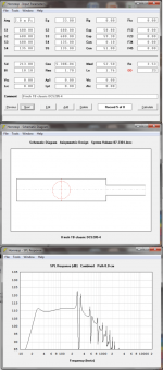
So here is what I've come up with using two 8" speakers from PE (Dayton Audio DCS205-4). Not too "bumpy" and the phase & group delays don't get too wild.
Now all I have to do is figure out how to implement this design in wood.
Now I am attempting to attach a file, so we shall see how it goes...
So here is what I've come up with using two 8" speakers from PE (Dayton Audio DCS205-4). Not too "bumpy" and the phase & group delays don't get too wild.
Now all I have to do is figure out how to implement this design in wood.
Now I am attempting to attach a file, so we shall see how it goes...
Attachments
you have enough space to utilize a single 8" driver tuned fairly low.
I think that's a great idea. I've just used HornResp to design a SINGLE speaker version of my project using an 8" woofer from PE. I can build TWO of these and try to place them in the room (2-8" speakers have almost the exact same area as 3-6.5" speakers). I can think of a couple of places they could go.3 drivers? Limited space? 3 amp channels available?
Consider building 3 single-driver units. One can be the plinth for the vase, the others can hide beside other pieces of furniture around the room. You'll get much more even bass response.
I will put up the drawings and HornResp numbers this evening. My NAD amp will put out a lot more power into 2 channels than 3-5 channels.
- Status
- This old topic is closed. If you want to reopen this topic, contact a moderator using the "Report Post" button.
- Home
- Loudspeakers
- Subwoofers
- Small Tower Subwoofer Project