I want to stay strictly with VSSA, no modifications, I just wanted to stay in this topic. Basically it says everything from 20-45V dc is OK. I surely don't need 60W, cause I decided that this amp is my private one for my small room  But lowering power too much is not OK too. Maybe I would just buy another trafo, with a bit smaller output voltage. I have to think about this
But lowering power too much is not OK too. Maybe I would just buy another trafo, with a bit smaller output voltage. I have to think about this  btw, with mod hat on
 Hi Renioo,I want to stay strictly with VSSA, no modifications, I just wanted to stay in this topic. Basically it says everything from 20-45V dc is OK. I surely don't need 60W, cause I decided that this amp is my private one for my small room
I built VSSA too, PeeCeeBee version
My mine use 25V AC from a 300VA trafo for stereo, the result is more than what I expected to...
No need class A for it, my VSSA bias around 200mA last time I measure it.
Maybe you need good preamp to feed it
In the early I'm joining here at diyAudio I want to build the class A one, the Hiraga 30 watt & now I don't think gonna build that monster
The thread title is a bit misleading right now I see
how about now ?
Hi ReniooI want to stay strictly with VSSA, no modifications

I see you have whole integrated amp project here, nice.

If you really want to stay strictly with VSSA and no modifications, speaking about power amp section, than use one SMPS400A180 per channel as recommended. Avoid heavy and noisy toroids, huge caps banks at 100 Hz pulsed DC, etc.

No matter that at this point will be only for your small room use, maybe some day in the future you will need more power and there it will be already present in your amp. SMPS will enable you efficient and noise free listening at low volume levels late at night, it already has soft start, speaker DC sense pin with shut down function if DC error appears on +SPK terminal, on board auxilary +/-21 V/500 mA supply for some low voltage parts of your integrated and some other candys.
Wish you pleasant work and good realization of the Small Amp project. Regards, Lazy Cat

Thanks for respond Lazy Cat. I would really like to use SMPS400A but it's way too expensive now. Maybe in near future I will buy one but now I have to stay with toroid Even though the amp is called Small, it already had eaten much funds However, DIY is much fun and following your VSSA was too! Thanks
Even though the amp is called Small, it already had eaten much funds However, DIY is much fun and following your VSSA was too! Thanks I had some issues with tube preamp, they picked up a bit of hum, but it wasn't big deal. There is something wrong with my PCB so I quickly made a small 1 solid-state preamp using BF245.
PCM1794 -56 ohm in series and parallel - bf245 - a bit too much of voltage and resistance for PCM (I think) caused a bit of distortion. I need more gain so I have to look for something bigger. Anyway, I'm pleased with what BF245 do and I have regulated supply for this one, so now I will stay with solid state preamp. Tubes will have their own box. Do you know any simple preamps using BF245 or similiar?
PCM1794 -56 ohm in series and parallel - bf245 - a bit too much of voltage and resistance for PCM (I think) caused a bit of distortion. I need more gain so I have to look for something bigger. Anyway, I'm pleased with what BF245 do and I have regulated supply for this one, so now I will stay with solid state preamp. Tubes will have their own box. Do you know any simple preamps using BF245 or similiar?
Attachments
![IMAG0276[1].jpg](/community/data/attachments/335/335161-94bd741a9523375d9371f029561bf8c6.jpg)
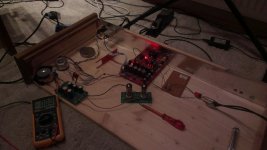
I got everything ! VSSA assembled and all the stuff, but there is a problem. VSSA is not running. I use 2x26V trafo (as above) connected to PSU (each 26V section to the seperate bridge and then to seperate caps and to VSSA). There should be around 35V on each VSSA, but there is 39V and 32V on each, setting the trimmer does change the offset (and voltage too) but there is nothing on input bias. Like it does not consumpt the power. PSU are grounded together in the star ground (with GND from VSSA too). Any ideas ?
?1) did you use the 20-22 Ohm resistors during setup?I got everything ! VSSA assembled and all the stuff, but there is a problem. VSSA is not running. I use 2x26V trafo (as above) connected to PSU (each 26V section to the seperate bridge and then to seperate caps and to VSSA). There should be around 35V on each VSSA, but there is 39V and 32V on each, setting the trimmer does change the offset (and voltage too) but there is nothing on input bias. Like it does not consumpt the power. PSU are grounded together in the star ground (with GND from VSSA too). Any ideas
2) If you did, what is the voltage drop across the resistor (you can divide that by the value of the resistor to see if excess current is being drawn by one of the rails)
3) if all that shows normal current drain, what is the DC voltage at the output? In other words, is the output pegged to one of the rails?
TP1 is 0,5V lower than +VDC. R19/20 are 10ohm.
The problem is I measured the rails from + to - not to GND (yea...) so they're about 17V. Which is not good when the trafo is 2x26V (26V between two wires). I just can't get it work normally. In every option it just lowers the voltage so much.
The problem is I measured the rails from + to - not to GND (yea...) so they're about 17V. Which is not good when the trafo is 2x26V (26V between two wires). I just can't get it work normally. In every option it just lowers the voltage so much.
- Status
- This old topic is closed. If you want to reopen this topic, contact a moderator using the "Report Post" button.
- Home
- Amplifiers
- Solid State
- Small Amp, Renioo Project