The fault is that the right hand channel will randomly make a loud crackling sound and blow my 1 Amp fuse connected inline with the speaker (I didn't trust this from the start and made speaker leads with 1A fuses!).
I may get a week of listening before it happens, or maybe 2 days, I spent an hour going over suspect joints (actually sucking up all the old solder and replacing it) and testing caps with my ESR meter. Does anyone have an idea what is going on??
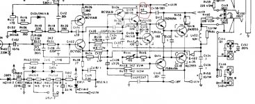
R438 is burning up when this fault occurs, and now has a black ring in the centre but it still measures ok and I am listening to the receiver now. I think Q410 may be going leaky when hot, but could be Q408 or anything really causing this chain reaction.
Has anyone spent time servicing this model that may be willing to throw some ideas at me? Or is the idea to throw this at a wall?
I may get a week of listening before it happens, or maybe 2 days, I spent an hour going over suspect joints (actually sucking up all the old solder and replacing it) and testing caps with my ESR meter. Does anyone have an idea what is going on??
R438 is burning up when this fault occurs, and now has a black ring in the centre but it still measures ok and I am listening to the receiver now. I think Q410 may be going leaky when hot, but could be Q408 or anything really causing this chain reaction.
Has anyone spent time servicing this model that may be willing to throw some ideas at me? Or is the idea to throw this at a wall?
Attachments
My instincts say that if this is not a dry joint etc then you should look at replacing the driver transistors (the 2SD669 and 2SB649). For no explainable reason these type of Japanese devices do fail open circuit base-emitter intermitently. MJE340/350 would be fine.
Also do check for dj's by actually resoldering the board. Sometimes it can be hard to spot a bad joint. Make sure the solder "takes" to the component as oxidation is a problem with many parts.
Also do check for dj's by actually resoldering the board. Sometimes it can be hard to spot a bad joint. Make sure the solder "takes" to the component as oxidation is a problem with many parts.
Thank you for your reply, I have just spent a while removing solder and reapplying solder to all main and suspect joints in the power amplifier section. I will thrash it for the next few days and see what happens. As a side note the top of the PCB actually measures a few megohm! Ah yes the classic NAD glue that conducts.... I made sure to clean it up, as where resistors are close it may just make a difference. I don't think this is the kind of amp you ever gain the confidence to remove your fused speaker leads!
Faults like this are the kind of thing you don't want for the safety of your speakers...
Personally I would replace the drivers on both channels and adjust the quiescent current to the correct value unless you are 100% sure you have found a problem joint... I have seen these fail (this type of TO126 packaged device) so many times and it's just not worth the risk. The very act of soldering them may temporarily "fix" them. I would also perhaps add the BD139 to the list.
If you can catch it in a faulty condition measuring across the base emitter junction (voltage) would reveal the problem.
It's just not worth the risk to your speakers.
Ah yes, the quiescent current. The service manual advises removing the short across a couple of resistors (one each channel) and measuring the voltage across them; I haven't found the bridge yet, but may have to take the bottom off tomorrow. I have set the amp to 8 Ohm mode to lower the supply rails. Tonight I will listen to music... It does throw a lot of heat out to be honest, but all NAD amps do this IMO.
I have set the amp to 8 Ohm mode to lower the supply rails.
Hi, AFAIK its the 4ohm setting that lowers the supply rails, rgds, sreten.
Hi Riotpack:
Some minutes ago, I finally finish fixing my 3225PE amp, that has exactly the same output stage, that you show in the schematic.
My amp also showed the hi-heating of R438, but was produced by a mistake made by me. I forgot to put the mica insulator below Q408 when I replaced it. After putting it again, the heat problem finished, but the output showed a 24 V voltage instead of 0 V d. c., and having a light bulb connected in series with the amp, as recommended in the service manual.
This other problem was caused by a leakage in Q402 between base and colector. Testing the transistor as two diodes, showed be in good shape, but when I measured resistance between leads, I found a strange value (1.8 kohm instead "OL" indication). This leakage moved the voltage at several transistor bases, moving to conduction some that should be in cut. After changing Q402 with a replacement (MPSA-06G, as I have not the BC550C at hand), the problem disappear and then I could do the center voltage and iddle current adjustments indicated in the service manual.
The solder bridge you need to remove to do the adjustments is in parallel with R456 (and R455 for the left channel).
I tested the amp for about one hour, listening some vinils and everithing was OK. (After two weeks of one or two hours night working).
Check the voltage at the colectors junction of Q402 and Q404. Probably will give you an indication of the cause of the failure.
Good look, and cheers.
Hugo.
Thanks for your reply, looks like I'll be ordering some parts in because after 2 days of listening to music my 1A speaker fuse blew yet again on the right channel, I didn't even hear the loud crackle this time.
Q404 Collector is 39.7V
Q402 Collector is 39.6V
Other channel is the same.
Sorry, something relevant I should have mentioned, This was an Ebay special and when it arrived the 4R/8R switch had been damaged and the 4A fuses were blown, I replaced both and it worked fine for about a week and here we are now.
Last edited:
Well, I should understand that this it is Ok. I used the right channel as reference, because the left one was broken. This help me to find the trouble. My speakers don't use fuses, because they increase its resistance with rising temperature. I know that this could produce a blown twetter or some like this, but I prefer to jeopardize it. You have not changed blown transistor yet, do you?. (Sorry, I am very lazy to read the previous postings).
Kind regards, from Querétaro.
Hugo.
Kind regards, from Querétaro.
Hugo.
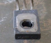
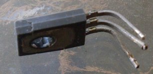
Wait a minute! That isn't sitting on an angle.. IT'S WARPED! Someone has replaced the output stage and tightened it up so much it cracked and the legs pushed it up. Well off to find some BD139s and hope this is all the problem is!
Attachments
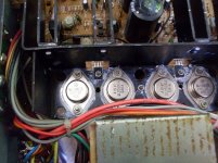
OK so I also found C416 1000u/6.3v to have a higher than usual ESR and looked to be bulging from the bottom.
I replaced that and the entire OP stage with MJ15003/4 and put new BD139s on both channels.
I haven't soldered the output stage in yet, but just before I was about to, I noticed something I had done would mean no sound! Can anyone see what it is??
Anyway I have put it aside till tomorrow.
(It is not the BD139s, they DO have insulators!)
Attachments
Last edited:
If someone has replaced the transistors from the original devices on this amp, it needs to be modded to include ballast resistors on the emitters, or it will be thermally unstable. The original devices used an old manufacturing process which tolerated the lack of ballast resistors but new "epitaxial" devices will not.
- Status
- This old topic is closed. If you want to reopen this topic, contact a moderator using the "Report Post" button.
- Home
- Amplifiers
- Solid State
- Slow failure of NAD 7225PE. Suggestions?