Hi, Baseballbat
That's interesting. How come you got bandwith up to 100khz with oscilation only 330khz? A little description?
I build a ClassD-Amp in my diploma, too, a modified UcD (with bandwidth up to 100kHz and a switching frequency around 330kHz). And it worked, with high loop gain. 30dB is enough, especially when provided over the whole frequency. The little phase shift near the cutoff frequency of the output filter can be ignored.
That's interesting. How come you got bandwith up to 100khz with oscilation only 330khz? A little description?
Hi lumanauw,
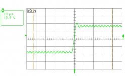
nothing special about it, just a first-order UcD at the limit.
The low switching frequency is no problem. An interesting paper about this is from Song/Sarwate: The Frequency Spectrum of Pulse Width Modulated Signals
I attached some impressive picture taken at the output of my amp. Looks nice, eh?
Bye
Baseballbat
Attachments
lumanauw said:Hi, Iand,
That's interestingWhat mechanism that makes Cuk needs higher voltage/current transistor?
Cuk converter has interesting equation, Vout=Vin*Ton/Toff.
It can magnify voltage or divide voltage, according to the ratio of Ton/Toff.
Is it possible to make big voltage swing with small voltage rail?
In Cuk converter (SMPS), after the capacitor there is only 1 diode. Why in Cuk classD, after the capacitor there is PNP transistor? What is this for, how does it work?
Before any output voltage swing the architecture means that each switch sees twice the output voltage, and carries a peak of double the output current for 50% of the time (output current=I, capacitor current=+/-I, switch current=2I or 0).
As soon as the output swings (duty cycle changes) the peak voltage on the switches goes up further, as does the peak current -- if you work out the equations from Cuk's papers you'll see why.
Even for a reasonable duty cycle range (0.4-0.6) which stops these peaks being ridiculously high, the peak switch voltage is around 3x the peak output voltage and the peak switch current is about 2.5x the peak output current, as in the figures I gave.
This compares to a conventional bridged class-D amplifier (same number of switches, 4) where the switch current and voltage are the same as for the load.
So the Cuk amplifier is hopeless at high powers due to cost and increased losses :-(
Ian
Somebody posted this schematic. The audio is here
http://www.diyaudio.com/forums/attachment.php?s=&postid=1386851&stamp=1199015903
PS is here
http://www.diyaudio.com/forums/attachment.php?s=&postid=1386852&stamp=1199015998
In the PS section, what kind of converter is around C11/L1/D9/D12/Q4 ? Is it a variant of Cuk Converter or somekind of capacitive-coupled buck converter?
lumanauw said:
What L - C value you use for output filter?
A UCD-style amplifier can give you a -3dB upper frequency point at over 60kHz into an 8 Ohm load using a 22uH and a 1uF.
Don't think about this as you would for a normal open-loop or pre-filter amplifier. The transfer function of a UCD amplifier is very different.
Back to the Cuk-based amp. I first saw that paper of Cuk's a few months ago and it interested me as I have been simulating a number of topologies for a class-D amplifier to give me 100V rms output, from a single 48V dc power rail, without the use of a step-up transformer. Obviously a conventional class-D output stage, based on a 4-quadrant buck regulator can't do this, but it is theoretically possible to make a class-D amplifier using a symetrical push-pull boost output stage which would give an output voltage in excess of the power rail. The problem with the approaches I've simulated so far (including the Cuk) is that they only have a small operating range in which the linearity is acceptable.
If you want to drive 100V paging audio lines, I think that boosting the voltage in a separate stage is the best approach. Think about it. You will end up using less inductors and capacitors and lower voltage transistors.
Consider either a synchronous boost stage producing 300V with a capacitive 150V center tap to which one end of the load is connected, and a half bridge stage fed from those 300V driving the other end of the load. This would use four 400V MOSFET, some hyperfast diodes to overcome body diodes, 2 supply electrolytics and 2 inductors. Alternatively, magnetic snubbers could be used for loss-less body diode switching.
Consider also a synchronous boost stage producing 150V and then a full bridge driving the load. This would use six 150V MOSFET, one supply electrolytic and three inductors.
Both approaches would allow to make 1000W 100V paging amplifiers with the size and weight of an ATX PC power supply.
Cuk is not practical due to the high switching voltage requirements and the poor performance of high voltage MOSFET.
On the other hand, two boost stages would require two sets of switches and two inductors, so there is no advantage. Furthermore, such a circuit is not particularly easy to control, while you can get hi-fi from a half bridge by making it self oscillating with the help of a single comparator.
Hi Eva. The conventional approach I'm going for at the moment is to produce +180V power rail and use a full-bridge to drive the load. I need 180V to give me enough headroom to meet the required power output when using a speech-shaped noise signal as the source. (higher crest factor than a sine wave).
It's just that some of the alternative approaches present some interesting design challenges!
It's just that some of the alternative approaches present some interesting design challenges!
Remember to include "four quadrant" current limiting on both outputs and clamping diodes to make it a bit more rugged against dumb installers and lousy installations
A boost power supply with floating output would be a good idea too, because 90V DC on outdoors 100V lines exposed to weather can corrode everything very quickly, unless one end of the full bridge is biased to earth and DC offset is minimal You can use linear optocouplers to transfer the signal.
Corroding due to DC in large wiring systems is a problem even indoors due to moisture. I have worked with that 100V stuff a few times in the past and indeed there were some good reasons to use transformer coupling.
I think that doing it the right way already presents enough challenges
A boost power supply with floating output would be a good idea too, because 90V DC on outdoors 100V lines exposed to weather can corrode everything very quickly, unless one end of the full bridge is biased to earth and DC offset is minimal
You can use linear optocouplers to transfer the signal.Corroding due to DC in large wiring systems is a problem even indoors due to moisture. I have worked with that 100V stuff a few times in the past and indeed there were some good reasons to use transformer coupling.
I think that doing it the right way already presents enough challenges
A floating 100V output is also a requirement of most emergency sound system standards for safety reasons. At least you can touch one of the outputs. To make sure that none of the outputs is accidentally connected to earth (e.g. damaged wiring insulation), an output earth leakage detector is needed that generates a fault condition.
A transformer output is still an easy way out, and offers the possibility of multiple secondaries, e.g. 25V for schools in the USA, 70V for other use in the USA, 100V for most other countries.
Steven
A transformer output is still an easy way out, and offers the possibility of multiple secondaries, e.g. 25V for schools in the USA, 70V for other use in the USA, 100V for most other countries.
Steven
Hi,
in the final version I used 18uH and 1uF, giving 37,5kHz. Of course, this low cutoff frequency reduces the loop gain at high frequencies, but I still had enough (15-20dB) at 100kHz, slightly depending on the attached load.
Bye
Baseballbat
lumanauw said:What L - C value you use for output filter?
in the final version I used 18uH and 1uF, giving 37,5kHz. Of course, this low cutoff frequency reduces the loop gain at high frequencies, but I still had enough (15-20dB) at 100kHz, slightly depending on the attached load.
Bye
Baseballbat
- Status
- This old topic is closed. If you want to reopen this topic, contact a moderator using the "Report Post" button.
- Home
- Amplifiers
- Class D
- Slobodan Cuk classD