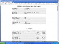
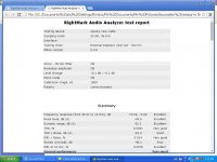
Well I've got the CFA-XH BV mod 2 going and it performs rather decently. It's certainly not by any means a bad amplifier spec wise. Not quite as good as the wolverine, but then we knew that anyway.
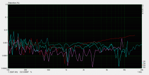
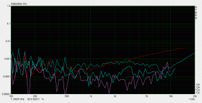
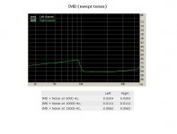
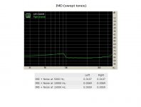
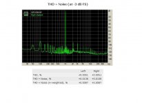
First up the amp delivering 2.83 volts into my 9.4 ohm load when optimally biased.

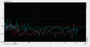
Next up the same, but this time biased into class A.

Down goes the 3rd harmonic and bye bye goes the 5th.
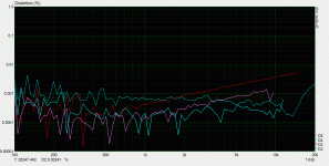
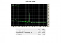
Now 14 v into the same load, optimally biased.

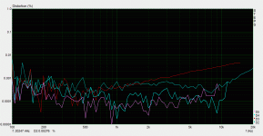
And the same as above but now in class A.

Biasing into class A does what you'd expect really, lowers distortion a little overall and makes a large difference to the higher order harmonics.
Someone will have to tell me if those numbers look right vs the sims.
At least we now have a decent benchmark for the CFA-XH BV mod.
Incidentally 14v is half the voltage swing that this amplifier will manage on 25 volt rails, which is what they are intended to be run off.
I will need to re-design my PCB a little as some stuff didn't work quite the way I had intended, but all in all it performs nicely.
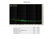
Incidentally here's the performance of 14v without any load connected.

This is almost identical to the class A biased version and clearly shows that the high levels of 3rd harmonic are not caused by the output stage.
Is this normal for the amplifier or are there some components within the amplifier that specifically need to be of a certain type for it to perform correctly? Like a film cap instead of a COG/NPO, or maybe using a higher wattage resistor somewhere?
First up the amp delivering 2.83 volts into my 9.4 ohm load when optimally biased.
Next up the same, but this time biased into class A.
Down goes the 3rd harmonic and bye bye goes the 5th.
Now 14 v into the same load, optimally biased.
And the same as above but now in class A.
Biasing into class A does what you'd expect really, lowers distortion a little overall and makes a large difference to the higher order harmonics.
Someone will have to tell me if those numbers look right vs the sims.
At least we now have a decent benchmark for the CFA-XH BV mod.
Incidentally 14v is half the voltage swing that this amplifier will manage on 25 volt rails, which is what they are intended to be run off.
I will need to re-design my PCB a little as some stuff didn't work quite the way I had intended, but all in all it performs nicely.
Incidentally here's the performance of 14v without any load connected.
This is almost identical to the class A biased version and clearly shows that the high levels of 3rd harmonic are not caused by the output stage.
Is this normal for the amplifier or are there some components within the amplifier that specifically need to be of a certain type for it to perform correctly? Like a film cap instead of a COG/NPO, or maybe using a higher wattage resistor somewhere?
Attachments
How looks card loopback with the same settings (input/output levels,Fs, window..)?
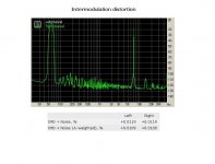
According simulation , realistic THD numbers in region 20-5kHz should be about 0,0003% (0.-9. harm), then rising to 0,0015% at 20kHz, 30VRMS, 8ohm load, 2 output pairs, optimal bias.
According simulation , realistic THD numbers in region 20-5kHz should be about 0,0003% (0.-9. harm), then rising to 0,0015% at 20kHz, 30VRMS, 8ohm load, 2 output pairs, optimal bias.
Last edited:
How looks card loopback with the same settings (input/output levels,Fs, window..)?
According simulation , realistic THD numbers in region 20-5kHz should be about 0,0003% (0.-9. harm), then rising to 0,0015% at 20kHz, 30VRMS, 8ohm load, 2 output pairs, optimal bias.
How looks card loopback with the same settings (input/output levels,Fs, window..)?
This will be interesting.
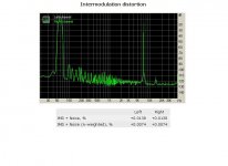
Can you make an fft measurement of this amplifier using ARTA?
Finally which is your sound card?
I am wondering if some of what Edmond was saying about most sound cards is playing a role here? Perhaps the noise floor isn't low enough on the standard cards to measure the extremely low distortion numbers that OS was showing in his simulations?
In my case at least i'm sure that numbers are not truth.
On the other side these measurements giving us a base for comparing between some INP
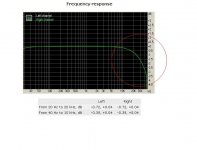
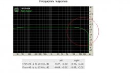
For example see these two photos.
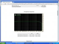
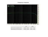
In the first photo is Spooky frequency response.
In the second,the same for CFA BV MOD.3
Attachments
Last edited:
thimios
You used voltage divider during those measurements. Think about internal impedance of this divider and interaction with vf filter at amp input. Was filter capacity the same?
You used voltage divider during those measurements. Think about internal impedance of this divider and interaction with vf filter at amp input. Was filter capacity the same?
I can not measure this amp, i did not built it, only simulations. I use Lynx L22 card, and it is capable to measure well down below 0,0001% at 1kHz.Can you make an fft measurement of this amplifier using ARTA?
Finally which is your sound card?
Oh sorry for this ,this is a job for Matt.thimios
You used voltage divider during those measurements. Think about internal impedance of this divider and interaction with vf filter at amp input. Was filter capacity the same?
I can not measure this amp, i did not built it, only simulations. I use Lynx L22 card, and it is capable to measure well down below 0,0001% at 1kHz.
Yes i used voltage divider and i will see and report about inp cap.filter soon.
Noise
Probably not. What I was saying was just a warning about using legacy PCI sound cards. If there are compatibility issues they will manifest themselves as cracks and plops and are easily detected.
Cheers, E.
Hi Steven,I am wondering if some of what Edmond was saying about most sound cards is playing a role here?
[snip]
Probably not. What I was saying was just a warning about using legacy PCI sound cards. If there are compatibility issues they will manifest themselves as cracks and plops and are easily detected.
Cheers, E.
Hi Ricky,Have little doubt. Platform controller hub link to CPU seems (4x link) PCIe (vX.X) both Intel or AMD, therefor seems some interfacing/bridging has to take place. Not shure but seems logic that inside platform controller hub is build in PCI-PCIe bridge though it's maybe a better brand or licensed one verse Z-chipset's where placed external. Shorter route than that could be made direct to CPU by PLX PCI-PCIe x1 link.
Not sure what you mean by "Have little doubt". Anyhow, the compatibility issues I was talking about are real and well known and discussed at length at the Lynx forum.
Cheers, E.
Hi Steven,
Probably not. What I was saying was just a warning about using legacy PCI sound cards. If there are compatibility issues they will manifest themselves as cracks and plops and are easily detected.
Cheers, E.
Unfortunately, for some cards there's no choice. For example, Lynx L22, which I like a lot and wish to buy one, exists only with legacy PCI interface

inp filter capac changed to 100pf(from680pf).
New measurements
Which amp?
Sorry this is cfa bv mod.3Which amp?

Not every motherboard with a modern -non-legacy- chip-set has issues with an Lynx. Please, have a look at: Lynx Support Forum Maybe you will find there a decisive answer.Unfortunately, for some cards there's no choice. For example, Lynx L22, which I like a lot and wish to buy one, exists only with legacy PCI interface
Cheers, E.
thimios,
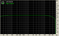
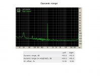
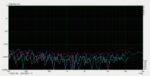
Now if is becoming much harder to see a real distinction between the two amplifiers, they are both looking good. I was wondering why the CFA was having such a large drop-off at high frequencies and now I see that has disappeared with your new measurements and a lower value capacitor on the input. I have been under the impression throughout the CFA vs VFA thread that the CFA would have the higher closed loop gain and bandwidth. I wonder how much lower the thd+n figures would be with a higher quality sound card for both amplifiers, it appears we are hitting the limits of your card Thimios.
Now if is becoming much harder to see a real distinction between the two amplifiers, they are both looking good. I was wondering why the CFA was having such a large drop-off at high frequencies and now I see that has disappeared with your new measurements and a lower value capacitor on the input. I have been under the impression throughout the CFA vs VFA thread that the CFA would have the higher closed loop gain and bandwidth. I wonder how much lower the thd+n figures would be with a higher quality sound card for both amplifiers, it appears we are hitting the limits of your card Thimios.
CFA-XH - Unmodified
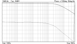
I'm using the Velleman PCSU1000 and PCGU1000 together to see what these amplifiers are doing. I see these designs as being high bandwidth and likely beyond what a soundcard can do in the upper frequency range. Attached is a Bode plot running form 100Hz to 5MHz. The -3db point occurs at ~300kHz and what looks like nice single pole response out to the limit of my gear.
EDIT: The input filter on the unit is 220R-470pF, so the cut-off is lower in my example than OS specified with 220R-100pF. The actual -3dB point is still lower than calculation would suggest but I also did not have the smaller compensation capacitors and used 100pF to be safe instead of the 33pF which may be impacting me bandwidth. Also the IPS is operating in isolation; there is no OPS attached to buffer the VAS from the low-Z feedback network and compensation. Still shows an order of magnitude better bandwidth than thimios' Bode plots show.
Attachments
Last edited:
Each cap exposed to AC voltage swing must be NPO type. So VAS compensation, input filter, local compensation in output stage...Is this normal for the amplifier or are there some components within the amplifier that specifically need to be of a certain type for it to perform correctly? Like a film cap instead of a COG/NPO
- Home
- Amplifiers
- Solid State
- Slewmaster - CFA vs. VFA "Rumble"