
Minimalist slewmaster.
I need little amps. Imagine that.
I have seen some quite interesting designs that integrate high efficiency bass/fullrange (2.1 systems) in a DIY setup.
One such setup used a tpa3112 for the sub , and a linear lm3886 for the L/R. The gentleman designed his own speakers - one of the best 2.1's I EVER heard. I discussed my class AB amp design experience with this person and traded amp designs for sub designs. His speakers were @ 100db/w and combined with a couple small slewmasters + the TPA , would "rock".
So a combined 50 + 50W wolverine and the tpa class D could match a much larger behemoth of a system. The LM3886 was quite good , but lacked what a proper AB discrete could do for the high end. Besides , what fun is designing a chip amp ?
OS
I need little amps. Imagine that.
Welcome back Pete!
I had same journey with my amplifier. The first version was designed to provide some 250W/4ohms, but the newer gives just half of it, and I feel it sounding better, build on same base...
Sajti
I need little amps. Imagine that.
...
Here a small but powerful amplifier (100W@8R / 200W@4R) using vertical mosfets IXTH80N20L and IXTH48P20P.
Test setup of SA2015-IXYS
Schematic in post #2185
BR, Toni
I need little amps. Imagine that.
Here's my version of the Slewmaster Mini one pair, should be good enough for 50W.
Attachments
I hope no more of mosfets perhaps these are romantic of sound, hehe
The legend of sound of Futterman big OTL power amplifier much of feedback and also a condensator to speaker have,but possible for good sound ,but take much of power i air only,much of heater current and so on, it was fun perhaps and magic of light.
Minimalism are also these tube amplifier with 300 B as single output power of about 8 watt ,but these 300 B are expensive components, transistor are more easy for use to little more of power from amplifier,sound are different i think.
I would not be surprised if he just burnt out.
But, if he isnt dead, he will be back IMO.
-Richard Marsh
Welcome back
-Richard

Help on CCS adjustment
I wish to make the Spooky amp....
Please tell me to adjust the CCS pots..
Regards,
Sumesh
Hello..Here's my version of the Slewmaster Mini one pair, should be good enough for 50W.
I wish to make the Spooky amp....
Please tell me to adjust the CCS pots..
Regards,
Sumesh
Hello..
I wish to make the Spooky amp....
Please tell me to adjust the CCS pots..
Regards,
Sumesh
Here's a testing process which was posted by on the stalwarts in this forum. I have used this process for my spooky based slewmaster.
Test the input separate from the output first. Put a 1k resistor from PD to the feedback connector and another 1k resistor from ND to the feedback connector. You should have around 11 volts between PD and ND and your DC offset measured at the feedback connector should be only a few mV. You can put a signal to input and read it at the feedback connector like this. Get your input board operating properly first before connecting to the output board. You should be getting 7.7mA across R22 if everything is working right too.
The output board can be tested by putting a 15k resistor from PD to V+ and another 15k resistor from ND to V-. Install 1 output pair and you should be able to set up your bias. I'm sure OS's feedback resistor scheme should work but I'm not familiar with it.
L1 - 1.5uH - 18 turns of 1.25mm wire, 12mm Diameter
You should use a bulb limiter when you are testing. It's a lot easier to see a 50 watt bulb out of the corner of your eye than to watch an ammeter on a limited supply. As you turn up your bias you should be able to see the bulb starting to glow.
After both halves are operating properly on their own, put them together and start testing again.
I fire mine up in sections. Fire up the outputs first with a bulb limiter in series with the mains and 15k resistors on the inputs. One from V+ to VD+ and one from V- to ND-. It's safest to do this with 1 output pair installed. The bias pot should be wound to the highest resistance setting. If the output board powers up without the bulb staying lit, try winding up the bias and see if you have control of the adjustment. Also measure DC on the speaker output. There shouldn't be much if everything is operating correctly. Bias should be 65 - 75mA, or around 30mV across a pair of emitter resistors. The bulb will light up as you increase the setting. If all is good turn down the bias and install all the output pairs, and check again. If all is good wind down the bias adjustment.
Fire up the input stages with their outputs disconnected from the output board and 1k resistors jumpered from PD+ to the NFB connection and from ND- to the NFB connection. Measure the voltage drop across R12. Adjust R19 so this is 3.8mA (3.8V). do the same with R13 and R10. After that's set, measure the voltage between PD+ and ND-. You should read around 11V if everything is working right. Also measure the DC offset at the NFB connection. I do this with the servo pulled out first just to see how good the input is matched, then with the servo in place. With the servo installed, there shouldn't be more than around 25mV present. If everything is well matched, it will be drifting around 2 or 3 mV.
The above is for the Spooky IPS.
If the input seems to be good, connect it to the output board and fire it up with the bulb still in place. Check for DC offset on the output and wind your bias up again. If you seem to have control of the bias, play some sine waves through the amp just to make sure everything is stable. The bulb will glow dimly as you slowly turn up the amplitude of the sine wave. If it goes from off to bright instantly, you probably have some oscillation. If all seems good, remove the bulb and start it up again. Set up your bias again and warm the amp up for a bit. You can just let it idle for a while, or cheat and hook up a load and play some sine waves. Keep checking the bias as it warms up. Also keep checking the temperature of the R137. If it's getting hot you likely have oscillation happening.
Once it's warmed up and if everything seems stable, it's time to listen to it and see what you think.
Last edited:
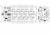
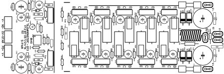
In my configuration i have to hold three large heatsinks together by using an aluminium sheet.The nuts and bolts have to be placed in specific positiions so i have to redesign the output stage as below and rearrange the output transistors having three pairs closely placed at the middle with the other 2 pairs placed a bit further away on each side.
Will i have any temperature issues or other issues with this arrangement?
Will i have any temperature issues or other issues with this arrangement?
Attachments
Last edited:
If your heatsinks aren't ideal the center transistors will run hotter than the two outside and will current hog. We saw this with the original Slewmaster boards too, that's why Pete did a second design with the larger spacing.
Can you post the second design? I only have the one below named v1.2.
Attachments
- Home
- Amplifiers
- Solid State
- Slewmaster - CFA vs. VFA "Rumble"