Physics applies whatever technology you use. Human nature applies whatever technology you use. Therefore increasing one parameter much higher than it needs to be always carries the risk of missing some other parameter. Being "creative and clever" just means you are more likely to be unaware of this.bimo said:If you use same method of ancient technology, I agree Just make amplifier with usual topology, blameless topology with usual compensation, the ordinary Miller compensation. You will go nowhere. If you more creative and clever, you can make it.
No, Mr. Fourier insists on it. All you need for a Fourier series is a periodic signal (so put the recording on repeat) with a finite number of finite discontinuities. Real music, however it is captured (including in our ears), has zero discontinuities. Therefore Fourier theory applies to music. If you don't want to repeat the music then you can do a Fourier transform instead.john curl said:Real transients are not actually just combinations of sine waves that slowly drop off with frequency, although a spectrum analyzer seems to imply it.
Does that mean the microphone is a source of slew rate limiting? It seems to be a longer time than a fast amp?Did you know that the B&K microphones used for recording by Mark Levinson, Crystal Clear direct disc recordings, and others have a rise-time of 9us?
Of course we can quibble, but several of us did and published the research approximately 40 years ago, and the measurements still show that a 10us rise-time waveform should be passed cleanly with hi fi rated audio equipment. For example, my 30ips analog recorder has a 10us rise-time, as does a TIM-30 test signal in my SR-1 (the easier TIM test).
If you can't pass a 10us risetime waveform, then you could have some TIM, the same goes if you ever play a vinyl record with an MC cartridge.
If you can't pass a 10us risetime waveform, then you could have some TIM, the same goes if you ever play a vinyl record with an MC cartridge.
9-10 us rise time is ~ 40 kHz BW according to the popular "0.35' factor for 1st order low pass
likewise citing SACD isn't impressive either - the standard calls for a higher order 50 kHz low pass filter for analog output - you should want to get ahead of the 5th order noise shaping that peaks +3 dB around 1.4 Mhz - pure digital bit banging noise
and of course a square wave has 1/n harmonic structure
It doesn't really work that way. Real transients are not actually just combinations of sine waves that slowly drop off with frequency, although a spectrum analyzer seems to imply it. They are caused by banging things together normally, or momentary clipping of a signal channel.
To understand this, just note what the rise-time of a 100Hz SQUARE WAVE can be. It can be almost infinite, YET the spectrum of the 100 Hz square wave looks pretty tame.
How about my scope calibration square wave? What do you think a 1ns rise-time does to audio equipment if you are not careful? Yet the spectrum analyzer will show typical musical rolloff.
No, you NEED a defined rise-time that is usually related to the closed loop bandwidth of the amp under test, and it could be fast enough to cause internal slew rate limiting of the very same amp. This is caused by high feedback in amps. Zero feedback amps do not have this problem. Usually we define a 10us rise-time as an appropriate test signal for testing solid state audio products.
Jeeeez... Mr. Curl, where have you learned these from? I couldn't think of a shorter text with a larger density of errors and misconceptions. It would take 3 times the size of your message only to enumerate these errors and misconceptions... Should I, or it would be a futile exercise?
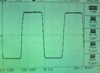
Nelson Pass likes to show scope photos of his amplifiers driving a 200 kHz square wave at 1 watt into 8 ohms. Here is one example, from the AudioExpress article about his F5 amplifier. Eyeballing the graticule divisions I'd call it 5.6V / 0.25usec = 22.4 volts/usec. Supply rail on the F5 is 21-22 volts so he's getting 1V/usec/volt.
_
_
Attachments
Last edited:
Nelson Pass likes to show scope photos of his amplifiers driving a 200 kHz square wave at 1 watt into 8 ohms. Here is one example, from the AudioExpress article about his F5 amplifier. Eyeballing the graticule divisions I'd call it 5.6V / 0.25usec = 22.4 volts/usec. Supply rail on the F5 is 21-22 volts so he's getting 1V/usec/volt.
_
You cannot read slew rate from an output with small swing like 5.6V. In a linear system, rise time is always same regardless amplitude. This would give you slew rate dependent on amplitude, which is a nonsense. You need to push the amplifier to slew rate limited region, when the output rises at almost constant slope. For this, you usually need to disconnect input RC filter, that limits the input BW. And/or you need to rise the output amplitude to such value when the output starts to "slew", i.e. rises with constant slope. From the NP's image it is impossible to tell the slew rate.
You cannot read slew rate from an output with small swing like 5.6V. In a linear system, rise time is always same regardless amplitude. This would give you slew rate dependent on amplitude, which is a nonsense. You need to push the amplifier to slew rate limited region, when the output rises at almost constant slope. For this, you usually need to disconnect input RC filter, that limits the input BW. And/or you need to rise the output amplitude to such value when the output starts to "slew", i.e. rises with constant slope. From the NP's image it is impossible to tell the slew rate.
Didn´t you mean the opposite?
Slew Rate is not amplitude dependent - by definition, as slew rate is the maximum rate of change the system is able to deliver - while rise time is, as it is usually measure in the non-slewing condition.
So if the amplifier in Mark Johnson´s example is already slewing then his estimate gives roughly the slew rate, if it´s not slewing then his estimate is roughly the lower bound.
")
Didn´t you mean the opposite?
Slew Rate is not amplitude dependent - by definition, as slew rate is the maximum rate of change the system is able to deliver - while rise time is, as it is usually measure in the non-slewing condition.
So if the amplifier in Mark Johnson´s example is already slewing then his estimate gives roughly the slew rate, if it´s not slewing then his estimate is roughly the lower bound.
From Mark Johnson's example one cannot tell if the amplifier is slewing or not.
I did not mean the opposite. For RC lowpass the rise time is always 2.2*RC, regardless the unit step amplitude. There is no "slew rate" there.
For amplifier or opamp, one usually needs to have certain amplitude to see slewing. Below that step amplitude it acts like a linear circuit.
Physics applies whatever technology you use. Human nature applies whatever technology you use. Therefore increasing one parameter much higher than it needs to be always carries the risk of missing some other parameter. Being "creative and clever" just means you are more likely to be unaware of this.
Of course, it must be have some trade-off. Several member here, can made good amplifier with high slew rate. Bob Cordell, Dadod, Vzaichenko, Ostripper.
I modify Apex's amplifier with simple modification to improve slew rate, THD, PSRR: AX11, AX14/16, and FH8 (http://www.diyaudio.com/forums/solid-state/295286-virtual-audition-very-simple-quasi-mosfet-amp.html)
and I made some another design, too.
Where is your amplifier design?
So an amplifier capable of delivering 100 Watts into an 8 ohm load, needs a slew rate of about 40 volts per microsecond to achieve the target I recommend.
Math: 100 watts = power = (Vrms * Vrms / 8 ohms) ; thus Vrms = 28.3 V
Vpeak = sqrt(2)*Vrms = 40 volts.
Minimum Acceptable Slew Rate = 1 V/us/volt * 40 volts = 40 V/us
I agreed and these requirements:
* 100 kHz amp working bandwith (minimum). And < 350 kHz to avoid problems with RFI / EMI.
* good records, with orchestral music (very fast transients).
@jcx,
Which isn´t wrong as the rate of change of a signal is that, but for an amplifier the slew rate is usually a feature of the device but not signal dependent, as it is in fact the maximum rate of change possible to get at the output of the device.
@PMA,
That´s why i provided both possible cases.
At that point we were talking about "rise time" not slew rate. You mentioned the _unit_ step function and the "unit" part is the reason why it is not amplitude dependent, as the unit step is just one unit.
But "rise time" is usually defined as the time span needed to rise from 10% signal level to 90% signal level and i think that illustrates why it depends on the amplitude. (And likewise the "fall time" as the time span needed to come down from 90% signal level to 10%)
As said above, the "slew rate" is a feature of the amplifier/device and is a typical large signal parameter.
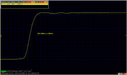
Your example below illustrates that, the amplifier obviously isn´t slewing the whole time but at a portion of the uprising part.
for many EE 'slew rate' is the time derivative of a signal
makes for some need to figure context when 'slew rate' is also being used for 'slew rate limit', 'maximum slew rate'
Which isn´t wrong as the rate of change of a signal is that, but for an amplifier the slew rate is usually a feature of the device but not signal dependent, as it is in fact the maximum rate of change possible to get at the output of the device.
@PMA,
From Mark Johnson's example one cannot tell if the amplifier is slewing or not.
That´s why i provided both possible cases.
I did not mean the opposite. For RC lowpass the rise time is always 2.2*RC, regardless the unit step amplitude. There is no "slew rate" there.
At that point we were talking about "rise time" not slew rate. You mentioned the _unit_ step function and the "unit" part is the reason why it is not amplitude dependent, as the unit step is just one unit.
But "rise time" is usually defined as the time span needed to rise from 10% signal level to 90% signal level and i think that illustrates why it depends on the amplitude. (And likewise the "fall time" as the time span needed to come down from 90% signal level to 10%)
As said above, the "slew rate" is a feature of the amplifier/device and is a typical large signal parameter.
Your example below illustrates that, the amplifier obviously isn´t slewing the whole time but at a portion of the uprising part.
You mentioned the _unit_ step function and the "unit" part is the reason why it is not amplitude dependent, as the unit step is just one unit.
But "rise time" is usually defined as the time span needed to rise from 10% signal level to 90% signal level and i think that illustrates why it depends on the amplitude. (And likewise the "fall time" as the time span needed to come down from 90% signal level to 10%)
.
I mentioned that the rise time (of the step response rising edge) does not depend on amplitude for a linear circuit like RC low pass filter. Of course not speaking about non-linear circuit like an amplifier.
And it is a fact! For RC low pass, Vout = Vo*(1 - exp(t/RC)), Vo amplitude of the step.
Tr(10% - 90%) does not depend on amplitude of the input step! Always Tr = 2.2*RC, you may calculate it, just use the equation above.
Maybe we have some kind of misunderstanding, but I am not going to step aside this fact.
Last edited:
Basics of Op Amp Gain Bandwidth Product and Slew Rate Limit
https://www.youtube.com/watch?v=UooUGC7tNRg
https://www.youtube.com/watch?v=UooUGC7tNRg
Your example below illustrates that, the amplifier obviously isn´t slewing the whole time but at a portion of the uprising part.
And that is where you will find and read the slew rate. For smaller step amplitude, you will see dual exponential-like response, resembling the linear circuit, 2RC.
Basics of Op Amp Gain Bandwidth Product and Slew Rate Limit
Yes, 2 different and often independent parameters. GBW is a small signal parameter, Slew Rate is a large signal parameter.
- Status
- This old topic is closed. If you want to reopen this topic, contact a moderator using the "Report Post" button.
- Home
- Amplifiers
- Solid State
- Slew Rate